1. Enter Scanner axis calibration (DS series)
1. Turn the power of all system components on, and start the software by clicking on the icon on your desktop.

2. After a few seconds the following dialog box appears.

3. Click Yes to reset the Scanner. The Scanner moves to position X0, Y0, Z10 (mm).
4. Click on the Config tab.
In the Scanner box, click on the Edit button to show the next dialog box.
5. Enter the handwritten settings into your Settings dialog box.
(Only DS series) The handwritten settings are unique to your

Scanner and are only available in the printed version of the manual.
6. Click on the Save button.
2. GPIB address of the spectrum analyzer
1. Click on the Config tab.
In the Spectrum analyzer box, click on the Communication settings button to show the next dialog box.

2. Enter the GPIB address of your spectrum analyzer into the GPIB Address box.
3. Click on the Save button.
4. Click on the Close button.
3. Positional calibration of the near field probe (DS and Rx series)
1. Place the near field probe in the probe holder. If the probe does not fit you can cut one of the spare probe holders to fit your probe.

2. Carefully move the Z-axis carriage by hand downwards until the limiting position switch is activated.

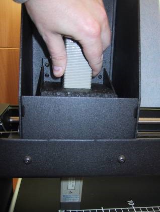
3. Place the probe holder and the probe in the Z-axis carriage (see picture). The probe should point straight down towards the Scanner.

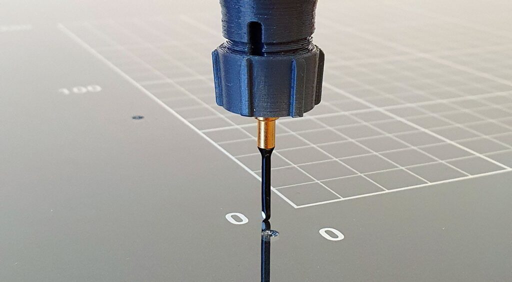
4. Carefully move the probe downwards until the tip of the probe touches the Scanner table.

5. Move the Z-axis carriage upwards until the lower limiting position switch is released.
6. Click on the Config tab. In the Scanner box, click the Reset button.
7. Measure the distance between the center of the probe tip and the origin of the coordinates of Scanner table.
8. Click on the Config tab. In the Spectrum analyzer box, near the Probe setting, click the Edit button.

9. Adjust the values of Origin Offset X and Y with the distances measured in step 7. For DS, RX and RQ scanners, do not change the value of Origin Offset Z. It should always be 10.
10. Click on the Save button.
11. Click on the Close button.
12. Click on the Config tab. In the Scanner box, click the Reset button.
Repeat step 6 to 12 until the tip of the
4. Positional calibration of the near field probe (HR series)
In the Scanner table of the HR Scanner there is a built-in transmitter that emits at 120MHz from two beacons located in the upper left corner of the grid on the Scanner table.
By using the SMA connector on the left side of the Scanner table, you can connect an external signal source that emits at a different frequency.
The purpose of the beacons is to calibrate the position of the near field probes in X and Y-axis. The two beacons are designed for different types of probes.
Click on the “Calibrate to Beacon button”

1. A dialog with 8 steps will guide you through the calibration process.
Step 1 : Make sure the Scanner table is empty.

2. Step 2 : Choose and connect the internal or external calibration signal source.

3. Step 3 : This is for safety to prevent the probe from running into the Scanner table.

4. Step 4 : Click the button “Reset to machine zero”. The Scanner resets and moves down to Z=0. The Scanner table must be empty.

5. Step 5 : Lower the probe holder cylinder. An easy way to calibrate the Z-axis is to use a thickness gauge between the tip of the probe and the table.

6. Step 6
Depending on the type of near field probe being used onr of the two beacons needs to be selected.
Beacon 1 is a vertical coil that works for H-field probes that are sensitive to a vertical field typically horizontal loop probes. This beacon also works for E-field probes. Beacon 2 is two crossed horizontal wires that work for H-field probes that are sensitive to a horizontal field typically vertical loop probes.
For best performance, a vertical loop probe must be rotated
so that the plane of the loop is aligned with the X or Y-axis.

7. Step 7 : Click on the Calibrate button to start the calibration sequence.The calibration will take between one and ten minutes depending on the speed of the spectrum analyzer. When the calibration is done you will be given a choice to move the probe to X0Y0Z0. It is recommended to do so. This is a chance to verify that the probe is correctly calibrated. If the calibration was successful the tip of the probe should be position directly above X0Y0. If the calibration if off you may need to adjust the starting position of the calibration. This can be done in the advanced settings. See below.

8. Step 8
Don’t forget to disconnect the calibration signal source

Advanced settings:
Clicking on “Advanced Settings” opens the dialog shown below. With these settings you can fine tune the calibration settings

1. Side length of starting area
The Scanner will search for the beacon in smaller and smaller squares. This is the size of the first big square.
Default value is 3.2mm
2. No. of avg. meas. / position
These are the number of measurements made at each measuring position, from which the average value is calculated. More measurements will give a more accurate result but will take longer. Default value is 10 measurements.
3. Center frequency (Int. beacon)
This is the frequency that will be measured when selecting Internal beacon in step 2 above. Default value is 120MHz
4. Center frequency (Ext. beacon)
This is the frequency that will be measured when selecting External beacon in step 2 above. Default value is 300MHz
5. Spectrum analyzer settings
These are the setting that will be used when searching for the beacon.
6. Start position probe type 1
These are the coordinates of the point around which we will start to search for the beacon when type 1 is selected in step 6 above.
7. Start position probe type 2
These are the coordinates of the point around which we will start to search for the beacon when type 2 is selected in step 6 above.
8. Return to factory settings
Click here to return to factory default settings.
5. Positional calibration of the near field probe (SCN-500 series)
1. Make sure the scanner table is empty.
2. Reset the scanner.

3. After reset you will get the choice to adjust the height of the probe. Click Yes.

4. Make sure that the probe is mounted heigh enough, or just remove the probe to be extra safe, before clicking OK to move down.

5. Lower the probe untill it almost touches the scanner table and fasten it.

6. Now the height (Z axis) of the probe is set.
7. If the tip of the probe is not located at the origin of coordinates then the origin offset values need to be adjusted.
8. Measure the distance between the center of the probe tip and the origin of the coordinates of Scanner table.

9. Click on the Config tab.
In the Spectrum analyzer box, near the Probe setting, click the Edit button.

10. Adjust the values of Origin Offset X and Y with the distances measured in step 8.
Please note! The value for Origin Offset Z is not in use for SCN-5xx series and must be set to zero.
11. Click on the Save and then the Close button.
12. Reset the scanner by repeating steps 2 – 4
13. Repeat step 8 to 12 until the tip of the probe is positioned above the origin of coordinates after a reset.
6. Laser Distance Meter (LDM) of SCN-500 series of EMC Scanners
The LDM is measuring the topography of a DUT using laser triangulation to create a 3D model (STL) that can be used to measure emission or immunity with the SCN-500 series of EMC Scanners.
The LDM is sending a laser beam straight down projecting a red dot on the surface of the DUT. A slightly angled camera built into the LDM registers the position the laser dot and the height is calculated by triangulation.
The LDM is attached on the left side of the ZR module of the SCN-500 EMC Scanner and connected at the top.

6.1. Preparations:
Before we begin calibration the position of the LDM we must make sure that the probe is properly calibrated to the coordinate grid. This can be done either manually or with the help of the Beacon calibration option.


6.2. Measuring the position of the LDM:
For the LDM to work properly it need to be calibrated in position. That is, the offset in X and Y of the laser beam compared to the probe must be typed into the software.
Measure the offset like this:
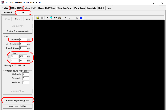
1. Go to Measuring Points tab – 3D.
2. Turn the laser on by checking LDM ON.
3. Click “Position Scanner manually” to open the positioning dialog.
4. Move the scanner head using the step-by-step movement buttons until the red laser dot is at the origin of coordinates.
5. Remember the X and Y position.
6. Turn the laser off.

6.3. Enter the LDM offset coordinates:
Enter the LDM offset coordinates:
1. Go to Config tab and click the Scanner Edit button.
2. Type in the reversed coordinates from the positioning dialog.
3. Click Save and then Close.

6.4. Measuring the topography of a DUT:
1. Place the DUT on the scanner table. Keep in mind that there is an area to the right where the laser cannot reach due to its position on the side of the probe.

2. Go to Meas. Points tab – 3D.
3. Enter the coordinates for an area that covers the DUT.
4. Enter the step size.
5. Click the button “Measure heights using LDM”.
6. Enter a filename for the 3D model in the “Save As” dialog that opens.
7. The scanning will begin.

8. When the scanning is done you can load the 3D model and it probably looks fairly good from the top view.

9. However, depending on the shape of the DUT and if the laser dot was blocked from the view of the camera, there may be some points where we have no good reading. If so, those points will show as unreasonably heigh spikes.

10. The feature “Auto correct heights” will find the points with bad readings and try to correct them by approximation from the surronding points.
11. Clicking “Auto correct heights” will open a “Save As” dialog and it is recommended to choose a different name and not overwrite the original 3D model just in case…

6.5. Tip:
Sometimes it is impossible to completely avoid bad readings because of the shape of the DUT but it is possible to reduce the number points in a few easy ways.
• Rotate the DUT so that steep edges are facing in the Y+ direction.
• Cover deep holes with non transparent tape.
• Cover shiny parts with non transparent tape.
7. Entering the amplitude correction factors of the near field probe
You can calibrate your probe, Pre-amp and cables automatically and accurately using Detectus Strip line calibration board and the self-explaining wizard found on the Config tab. The Strip line calibration board is sold separately and requires a spectrum analyzer with built-in tracking generator. Make sure the scanner table is empty.
1. Click on the Config tab.
In the Spectrum analyzer box, near the Probe setting, click the Edit button.

2. Enter a new name for the probe setting in the Probe text box. Please note that the name must begin with PROBE_.

3. Click the … button to edit the Correction factors.
Enter the frequency in Hz, kHz, MHz or GHz. Enter the amplitude correction in dB.

4. Click on the OK button.
5. Click on the Close button.
8. Positional calibration of the IRprobe (DS, and Rx series)
1. Place the IR-probe in the Z-axis carriage. The probe should point straight down towards the Scanner.
2. Click on the Config tab.
In the Scanner box, click the Reset button.
3. Press the LASER ON button on top of the IR-probe.
A diode will light a red spot on the Scanner for app. 15 seconds.
4. Measure the distance between the light spot and the origin of coordinates of the Scanner table.
5. Click on the Config tab.
In the Spectrum analyzer box, near the Probe setting, click the Edit button.

6. Adjust the values of Origin Offset X and Y with the distances measured in step 4. For DS, RX and RQ scanners, do not change the value of Origin Offset Z. It should always be 10.
7. Click on the Save button.
8. Click on the Close button.
9. Click on the Config tab. In the Scanner box, click the Reset button.
10. Repeat step 2 to 9 until the light spot is positioned at the origin of coordinates after a reset.
9. Calibrating the temperature reading of the IR-probe (DS and Rx series)
To be able to perform the calibration, you need two surfaces of different temperatures. A big difference in temperature between the two surfaces will generate a better result than a small difference in temperature. The temperatures of the surfaces need to be fairly stable during the calibration process.
9.1. Calibrating the temperature (°C) reading of the IR-probe is done in three steps:
1. Setting calibration factors to default values.
2. Calculating the calibration gain.
3. Calculating the calibration offset.
9.2. Setting calibration factors to default values
1. Click on the Config tab. In the Scanner box, click on the Edit button to show the next dialog box.

2. Make sure that the Heat calibration gain is set to 2.22 and that the Heat calibration offset is set to 0 (zero).
3. Click on the Save button.
4. Click on the Close button.
9.3. Calculating calibration gain
1. Point the IR-probe towards a surface with a low constant temperature, e.g. the black surface on top of the Scanner table.
2. Click on the Meas. Heat tab.
3. In the Measure Continuously box, click on the button Measure Now button.

4. Make notes on the temperature reading on the screen and the temperature reading on the LCD display of the IR-probe.
5. Now point the IR-probe towards a surface with a high constant temperature.
6. Make notes on the temperature reading on the screen and the temperature reading on the LCD display of the IR-probe.
7. Calculate the new calibration gain using this formula: SCR1 = Low temperature shown on the screen.
LCD1 = Low temperature shown on the LCD display of the IR-probe.
SCR2 = High temperature shown on the screen.
LCD2 = High temperature shown on the LCD display of the IR-probe.
New calibration gain = (LCD2 – LCD1)/ (SCR2 – SCR1)*Old calibration gain
8. Cick on the Config tab.
In the Scanner box, click on the Edit button to show the next dialog box.

9. Enter the new Heat Calibration gain
10. Click on the Save button.
11. Click on the Close button.
12. Repeat the procedure until (LCD2 – LCD1)/ (SCR2 – SCR1) is near one.
9.4. Calculating calibration offset
1. Point the IR-probe towards a surface with a constant temperature, e.g. the black surface on top of the Scanner table.
2. Click on the Meas. Heat tab.
3. In the Measure Continuously box, click on the button Measure Now button.

4. Make notes on the temperature reading on the screen and the temperature reading on the LCD display of the IR-probe.
5. Calculate the new offset factor using this formula:
SCR = temperature shown on the screen.
LCD = temperature shown on the LCD display of the IR-probe
New calibration offset = LCD – SCR + old calibration offset.
6. Click on the Config tab.
In the Scanner box, click on the Edit button to show the next dialog box.

7. Enter the new Heat Calibration gain.
8. Click on the Save button.
9. Click on the Close button.
10. Repeat the procedure until the temperature reading on the screen and the temperature reading on the LCD display of the IR-probe are equal.
9.5. Changing the heat emission factor of the IR probe
The emission factor is the rate of energy emitted from the surface of the object in front of the probe. All objects possess a particular emission factor which changes according to the object’s conditions or temperature. Since the probe allows the emission factor to be set, even more precise measurements can be conducted by matching the emission factor of the object to be measured.
Objects with a low emission factor (e.g the surface of shiny metallic objects) reflect the surrounding temperature since they are reflective. In this case, it is necessary to block out these effects from the surrounding objects since incorrect measurements will result by reflecting these temperatures.
The emission factor normally has a maximum value of 1.00. However, taking into consideration the influence of the surrounding noise, the emission factor of the probe can be set up to 1.20.
9.6. This is how to change the emission factor of the probe:
1. Unscrew and remove the cover.

2. Press the enter button to enter setup mode. The button will light red.

3. Press arrow buttons until the cursor on the display is above the “ε”

4. Press the enter button to select the emissivity setting mode.
5. Press the arrow buttons to adjust the emission factor.
6. Press the enter button to exit the emissivity setting mode.
7. Press the enter button to exit the setup mode.
8. Mount to cover.