1. Preparations:
Before we begin calibration the position of the LDM we must make sure that the probe is properly calibrated to the coordinate grid. This can be done either manually or with the help of the Beacon calibration option.


2. Measuring the position of the LDM:
For the LDM to work properly it need to be calibrated in position. That is, the offset in X and Y of the laser beam compared to the probe must be typed into the software.
Measure the offset like this:
1. Go to Measuring Points tab – 3D.
2. Turn the laser on by checking LDM ON.
3. Click “Position Scanner manually” to open the positioning dialog.
4. Move the scanner head using the step-by-step movement buttons until the red laser dot is at the origin of coordinates.
5. Remember the X and Y position.
6. Turn the laser off.

3. Enter the LDM offset coordinates:
Enter the LDM offset coordinates:
1. Go to Config tab and click the Scanner Edit button.
2. Type in the reversed coordinates from the positioning dialog.
3. Click Save and then Close.

4. Measuring the topography of a DUT:
1. Place the DUT on the scanner table. Keep in mind that there is an area to the right where the laser cannot reach due to its position on the side of the probe.

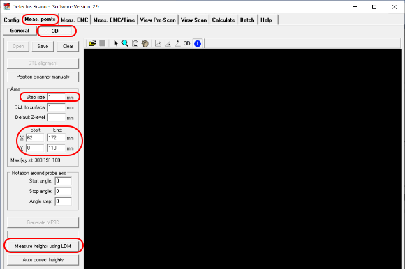
2. Go to Meas. Points tab – 3D.
3. Enter the coordinates for an area that covers the DUT.
4. Enter the step size.
5. Click the button “Measure heights using LDM”.
6. Enter a filename for the 3D model in the “Save As” dialog that opens.
7. The scanning will begin.

8. When the scanning is done you can load the 3D model and it probably looks fairly good from the top view.

9. However, depending on the shape of the DUT and if the laser dot was blocked from the view of the camera, there may be some points where we have no good reading. If so, those points will show as unreasonably heigh spikes.

10. The feature “Auto correct heights” will find the points with bad readings and try to correct them by approximation from the surronding points.
11. Clicking “Auto correct heights” will open a “Save As” dialog and it is recommended to choose a different name and not overwrite the original 3D model just in case…

5. Tip:
Sometimes it is impossible to completely avoid bad readings because of the shape of the DUT but it is possible to reduce the number points in a few easy ways.
• Rotate the DUT so that steep edges are facing in the Y+ direction.
• Cover deep holes with non transparent tape.
• Cover shiny parts with non transparent tape.