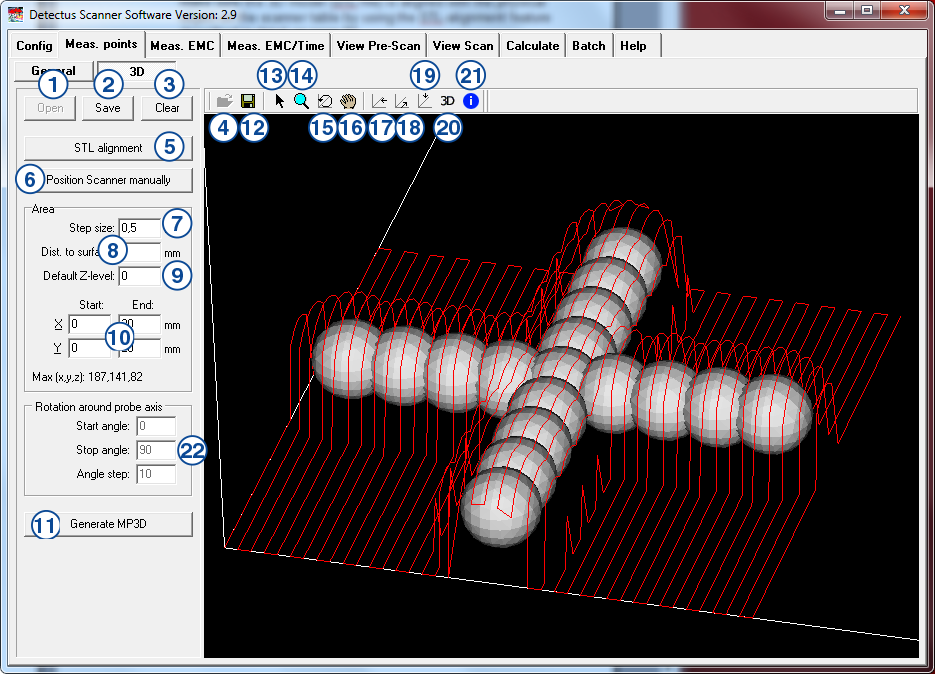
On this tab, you define the measuring points as an offset to a 3d surface model.

1. Open
Click here to load a previously saved set of measuring points. The files containing 3D measuring points are named *.MP3D.
2. Save
Click here to save a set of measuring points to an *.MP3D file.
3. Clear
Click here to unload MP3D and STL files.
4. Load STL file
Click here to load a 3d surface model in binary STL file format.
5. STL alignment
Click here to open the STL alignment dialog. See page 103.
6. Position Scanner manually
Click on this button to open the form shown below: For details please refer to page 105.

7. Step size
Step size is the distance between measuring points.
A small step size will generate a high-resolution measurement and a large step size will generate a low-resolution measurement.
Measuring in large steps is quicker than measuring in small steps.
8. Dist. To surface
The distance between the surface of the STL file to the measuring points.
9. Default Z-level
The height of the measuring points that are beside the STL surface model. This is the lowest possible height of a measuring point.
10. Start and stop for X and Y
These values define the measuring area in the XY-plane.
11. Generate MP3D
Click here to start generating measuring points.
12. Save STL file
Click here to save the surface model in its current position to a binary STL file.
13. Information mode
Click on this button to activate Information mode.
When Information mode is activated, the following features are available:
- a. Place the pointer on a measurement and you will see its file name along with the coordinates of the point at which you are pointing. If the measurement in question is an EMC-Scan measurement, you will also see the frequency of the highest peak.
- b. Rotate the view in 3D by keeping the left mouse button pressed down as you move the pointer.
- c. Pan the view in 3D by keeping the right mouse button pressed down as you move the pointer.
- d. Zoom in or out by turning the mouse wheel.
14. Zoom mode
Click on this button to activate Zoom mode.
When Zoom mode is activated, the following features are available:
- a. Zoom in or out by turning the mouse wheel.
- b. Zoom in or out by keeping the left mouse button pressed down as you move the pointer.
15. Rotate mode
Click on this button to activate Rotate mode.
When Rotate mode is activated, the following features are available:
- a. Rotate the view in 3D by keeping the left mouse button pressed down as you move the pointer.
- b. Zoom in or out by turning the mouse wheel.
16. Pan mode
Click on this button to activate Pan mode.
When Pan mode is activated, the following features are available:
- a. Pan the view in 3D by keeping the left mouse button pressed down as you move the pointer.
- b. Zoom in or out by turning the mouse wheel.
17. Side view
Click on this button to rotate and view the measurements from the side.
18. Front view
Click on this button to rotate and view the measurements from the front.
19. Top view
Click on this button to rotate and view the measurements from the above.
20. 3D
Click on this button to enable 3D mode.
21. Information
Click this button to show and hide the information window.
22. Rotation around probe axis
These values define the rotation around the probe axis.
This feature is only available for Scanner models HR41 and HR43.