On this tab, you define the measuring points. The measuring points can either make up a grid of points or just be individual points on specified positions.
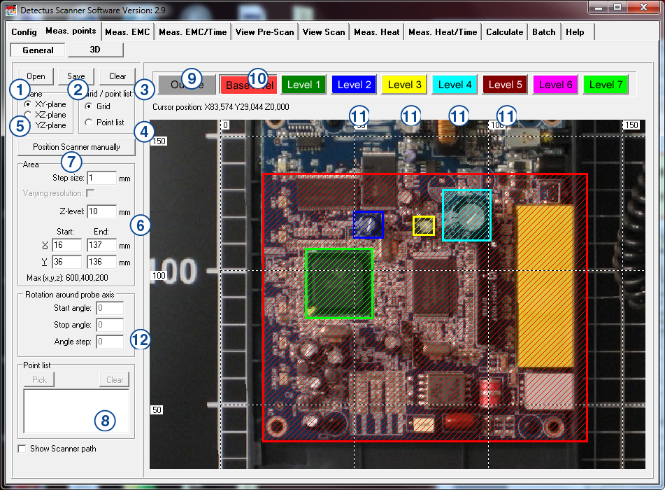
1. Open
Click here to load a previously saved set of measuring points. The files containing measuring points are named *.MP.
2. Save
Click here to save a set of measuring points to an *.MP file.
3. Clear
Click here to clear all settings on this tab.
4. Grid/Point list
The option Grid will enable you to define a grid of measuring points. The option Point list will enable you to Pick individual points for measuring.
5. Plane
Select the orientation of the measuring plane.
6. Area
In this box, you define the area, step size and height of the currently selected level. (The level is selected by clicking on one of the buttons Outline, Base level, Level 1, Level 2, Level 3 and so on)
The settings in this box are valid only when Grid is selected in the Grid/Point list box.
Start X, End X, Start Y and End Y:
These values define an area aligned with the currently selected Plane. The values can be entered either manually into the text boxes or by clicking and drawing on the graphics.
Step size:
Step size is the distance between measuring points.
A small step size will generate a high-resolution measurement and a large step size will generate a low-resolution measurement.
Measuring in large steps is quicker than measuring in small steps.
Z-level:
Z-level is the height of the probe above the Scanner table during measurement.
Varying resolution:
This is not a setting. It is just an indication that different step sizes are being used on different planes.
Point list, Pick
Click this button to activate Pick mode. (Pick mode is activated when this button appears to be pressed down and the hair-cross pointer is visible.)
When Pick mode is activated you can point and click on the graphics to pick the X and Y coordinates of a measuring point. Unless you point and click on a previously defined area, a dialog box will appear, and ask you to enter the height of the point you have just picked.
Point list, Clear
Click this button to clear the point list.
Point list
The point list can be edited manually just like an ordinary text box.
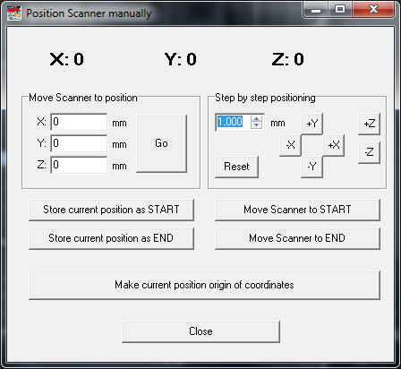
7. Position Scanner manually
Click on this button to open the form shown below:
For details please refer to page 105.
8. Show Scanner path
Check this option to show the path along which the Scanner will move during measurement.
9. Outline
Click on this button to select the Outline for editing. Edit the properties of Outline either by changing the values in the Area box, or by clicking and drawing on the graphics.
The sole purpose of Outline is to help you document the position of the test object on the Scanner table.
10. Base level
Click on this button to select the Base level for editing. Edit the properties of Base level either by changing the values in the Area box, or by clicking and drawing on the graphics.
Base level defines the area to be measured.
11. Level 1, Level 2, Level 3, and Level 4.
Click on one of the buttons to select the desired level for editing. Edit the properties of level either by changing the values in the Area box, or by clicking and drawing on the graphics.
The purpose of these levels is to make it possible to define islands of different height, so that the probe will not run into a high component.
A level with higher number has higher priority than a level with lower number. This means that if two, or more, levels coincide at a measuring position, then the height of the level with the highest number will be used.
12. Rotation around probe axis
These values define the rotation around the probe axis.
This feature is only available for Scanner models HR41 and HR43.