1. Check List
The shipment should contain the following:
- Counter/Timer/Analyzer CNT-90/91 or Frequency Calibrator/Analyzer CNT-91R or CNT-91R/AF or Microwave Counter/Analyzer CNT-90XL
- Line cord
- Brochure with Important Information
- Certificate of Calibration
- Options you ordered should be installed. See Identification below.
- CD including the following documentation in PDF:
- Getting Started Manual
- User’s Manual
- Programmer’s Handbook
2. Identification
The type plate on the rear panel shows type number and serial number. See illustrations on page 2-5 and 2-6. Installed options are listed under the menu User Options – About, where you can also find information on firmware version and calibration date. See page 2-15. The CNT-91R/AF version is identified by a unique identification marking, or UID. This permanent tag contains a barcode and allows customers to track easily their inventory and property.
3. Installation
3.1. Supply Voltage
Setting
The Counter may be connected to any AC supply with a voltage rating of 90 to 265 Vrms, 45 to 440 Hz. The counter automatically adjusts itself to the input line voltage.
Fuse
The secondary supply voltages are electronically protected against overload or short circuit. The primary line voltage side is protected by a fuse located on the power supply unit. The fuse rating covers the full voltage range. Consequently, there is no need for the user to replace the fuse under any operating conditions, nor is it accessible from the outside.
CAUTION: If this fuse is blown, it is likely that the power supply is badly damaged. Do not replace the fuse. Send the counter to the local Service Center.
Removing the cover for repair, maintenance and adjustment must be done by qualified and trained personnel only, who are fully aware of the hazards involved.
The warranty commitments are rendered void if unauthorized access to the interior of the instrument has taken place during the given warranty period.
3.2. Battery Supply
CNT-90 & CNT-90XL only
It is possible to run the counter from an optional battery supply, Option 23/90. You must charge the battery before use or storage. The counter charges the battery automatically when connected to line power or an external DC source, whether the instrument is in standby or turned on. See the specifications for charging time in different modes of operation.
3.3. Grounding

Grounding faults in the line voltage supply will make any instrument connected to it dangerous. Before connecting any unit to the power line, you must make sure that the protective ground functions correctly. Only then can a unit be connected to the power line and only by using a three-wire line cord. No other method of grounding is permitted. Extension cords must always have a protective ground conductor.
CAUTION: If a unit is moved from a cold to a warm environment, condensation may cause a shock hazard. Ensure, therefore, that the grounding requirements are strictly met.
WARNING: Never interrupt the grounding cord. Any interruption of the protective ground connection inside or outside the instrument or disconnection of the protective ground terminal is likely to make the instrument dangerous.
3.4. Orientation and Cooling
The counter can be operated in any position desired. Make sure that the air flow through the ventilation slots at the top, and side panels is not obstructed. Leave 5 centimeters (2 inches) of space around the counter.
3.5. Fold-Down Support
For bench-top use, a fold-down support is available for use underneath the counter. This support can also be used as a handle to carry the instrument.

3.6. Rackmount Adapter

If you have ordered a 19-inch rack-mount kit for your instrument, it has to be assembled after delivery of the instrument. The rackmount kit consists of the following:
- 2 brackets, (short, left; long, right)
- 4 screws, M5 x 8
- 4 screws, M6 x 8
WARNING: Do not perform any internal service or adjustment of this instrument unless you are qualified to do so. Before you remove the cover, disconnect mains cord and wait for one minute. Capacitors inside the instrument can hold their charge even if the instrument has been separated from all voltage sources.

3.7. Assembling the Rackmount Kit (Option 22/05)
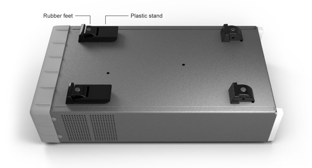
- Turn the devices upside down
- Remove the rubber feet in the plastic stand
- Loosen the screws underneath the rubber feet
- Remove the plastic stands
- Remove the four decorative plugs that cover the screw holes on the right and left side of the front panel.
Use the following steps to complete the side by side rack mount installation for your products. If necessary, refer to the item numbers in the following diagram for additional detail.
- Determine where you would like each unit positioned (i.e., on the right or left side)
- If plugs exist on the mounting holes on the front left and right side of product cover, remove and discard them
- Using screwdriver, screw the rack ear (Item #2) into place using the supplied 10mm screws (Item #5)
- Pinch the hinge pins together to separate the right and left hinge halves (Items #3 and 4)
- Attach hinge halves to the unit with hinge facing towards the front (as displayed in diagram)
- Using a screwdriver, remove the existing rear brackets on the back of each unit
- Using existing machine screws removed in previous steps, attach the rear brackets supplied with the mounting kit (Item #1)
- Pinch the hinge pins together into the stored position. Align the hinge halves together between the two units, and swing together side by side. The hinge pins should snap into place securing the front of the two units together
- Take the supplied Hex Spacer (Item #7) and place between middle rear brackets, and secure using the supplied 8mm screws (Item #6)
- Assembly is now ready for installation into standard 19” rack
