1. Trigger Hysteresis
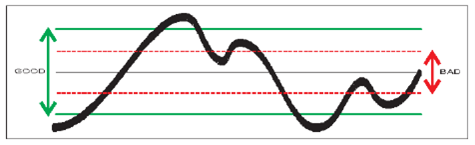
The signal needs to cross the 20 mV input hysteresis band before triggering occurs. This hysteresis prevents the input from self-oscillating and reduces its sensitivity to noise. Other names for trigger hysteresis are “trigger sensitivity” and “noise immunity”. They explain the various characteristics of the hysteresis.
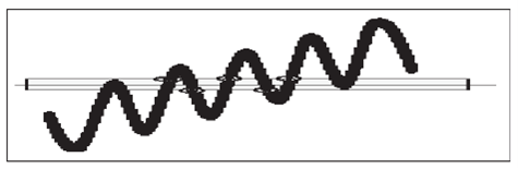
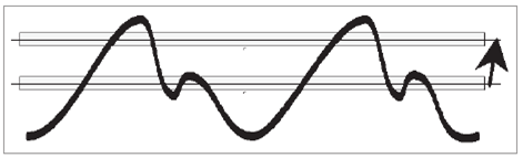
Fig. 3-10 and Fig. 3-12 show how spurious signals can cause the input signal to cross the trigger or hysteresis window more than once per input cycle and give erroneous counts.
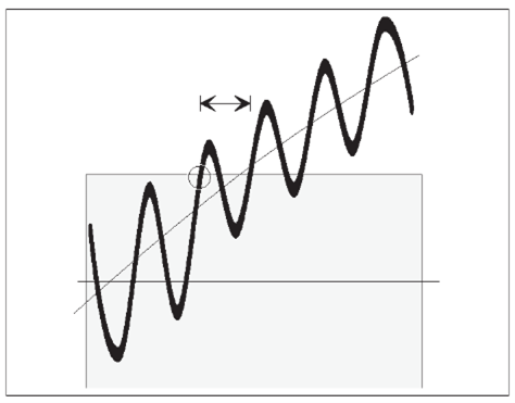
Fig. 3-13 shows that less noise still affects the trigger point by advancing or delaying it, but it does not cause erroneous counts. This trigger uncertainty is of particular importance when measuring low frequency signals, since the signal slew rate (in V/s) is low for LF signals. To reduce the trigger uncertainty, it is desirable to cross the hysteresis band as fast as possible.
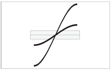
Fig. 3-14 shows that a high amplitude signal passes the hysteresis faster than a low amplitude signal. For low frequency measurements where the trigger uncertainty is of importance, do not attenuate the signal too much, and set the sensitivity of the counter high.
In practice however, trigger errors caused by erroneous counts (Fig. 3-10 and Fig. 3-12) are much more important and require just the opposite measures to be taken.
To avoid erroneous counting caused by spurious signals, you need to avoid excessive input signal amplitudes. This is particularly valid when measuring on high impedance circuitry and when using 1 MW input impedance. Under these conditions, the cables easily pick up noise.
External attenuation and the internal 10x attenuator reduce the signal amplitude, including the noise, while the internal sensitivity control in the counter reduces the counter’s sensitivity, including sensitivity to noise. Reduce excessive signal amplitudes with the 10x attenuator, or with an external coaxial attenuator, or a 10:1 probe.
2. How to use Trigger Level Setting
For most frequency measurements, the optimal triggering is obtained by positioning the mean trigger level at mid amplitude, using either a narrow or a wide hysteresis band, depending on the signal characteristics.
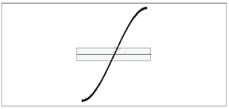
When measuring LF sine wave signals with little noise, you may want to measure with a high sensitivity (narrow hysteresis band) to reduce the trigger uncertainty. Triggering at or close to the middle of the signal leads to the smallest trigger (timing) error since the signal slope is steepest at the sine wave center, see Fig. 3-15.
When you have to avoid erroneous counts due to noisy signals, see Fig. 3-12, expanding the hysteresis window gives the best result if you still center the window around the middle of the input signal. The input signal excursions beyond the hysteresis band should be equally large.
Auto Trigger
For normal frequency measurements, i.e. without arming, the Auto Trigger function changes to Auto (Wide) Hysteresis, thus widening the hysteresis window to lie between 70 % and. 30 % of the peak-to-peak amplitude. This is done with a successive approximation method, by which the signal’s MIN. and MAX. levels are identified, i.e., the levels where triggering just stops. After this MIN./MAX. probing, the counter sets the trigger levels to the calculated values. The default relative trigger levels are indicated by 70 % on Input A and 30 % on Input B. These values can be manually adjusted between 50 % and 100 % on Input A and between 0 % and 50 % on Input B. The signal, however, is only applied to one channel.
Before each frequency measurement the counter repeats this signal probing to identify new MIN/MAX values. A prerequisite to enable AUTO triggering is therefore that the input signal is repetitive, i.e., >100 Hz (default). Another condition is that the signal amplitude does not change significantly after the measurement has started.
NOTE: AUTO trigger limits the maximum measuring rate when an automatic test system makes many measurements per second. Here you can increase the measuring rate by switching off this probing if the signal amplitude is constant. One single command and the AUTO trigger function determines the trigger level once and enters it as a fixed trigger level.
Manual Trigger
Switching to Man Trig also means Narrow Hysteresis at the last Auto Level. Pressing AUTOSET once starts a single automatic trigger level calculation (Auto Once). This calculated value, 50 % of the peak-to-peak amplitude, will be the new fixed trigger level, from which you can make manual adjustments if need be.
Harmonic Distortion
As rule of thumb, stable readings are free from noise or interference.
However, stable readings are not necessarily correct; harmonic distortion can cause erroneous yet stable readings. Sine wave signals with much harmonic distortion, see Fig. 3-17, can be measured correctly by shifting the trigger point to a suitable level or by using continuously variable sensitivity, see Fig. 3-16. You can also use Trigger Hold-Off, in case the measurement result is not in line with your expectations.