Preface
Please refer to User Manual for general description of instrument operation, measurement principles and concepts.
Introduction to SCPI
What is SCPI?
SCPI (Standard Commands for Programmable Instruments) is a standardized set of text-based commands used to remotely control programmable test and measurement instruments. It defines the syntax and semantics that a controller must use to communicate with the instrument. This manual is an overview of SCPI and shows how SCPI is used in Pendulum CNT-104S instrument. SCPI is based on IEEE-488.2 to which it owes much of its structure and syntax.
Syntax and style
Syntax of Program Messages
In SCPI all messages that you can send to an instrument are divided into two categories: commands (that do not imply getting any response) and queries (that allow to get response back from the instrument). Queries have question mark ('?') at the end of command header.
A command or query is called a program message unit. A program message unit consists of a header followed by zero or more parameters:
<header> [parameter [,parameter ,...]]
For example, in the query
FETCH:ARRAY? MAX, A
FETCH:ARRAY is a header and MAX and A are parameters.
One or more program message units (commands) may be sent within a simple program message:
<program message unit>; <program message unit>; <program message unit>...
For example,
:INIT; *OPC?
Common Commands
SCPI standard defines a set of commands that every instrument must support. The common command header starts with the asterisk character (*), for example *RST.
SCPI Commands Tree
SCPI command headers may consist of several keywords (mnemonics), separated by the colon character (:).
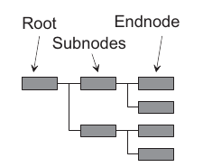
Each keyword in a SCPI command header represents a node in the SCPI command tree. The leftmost keyword is the root level keyword, representing the highest hierarchical level in the command tree.
The keywords following represent subnodes under the root node.
Example: :SYST:CONF "Sample Interval=15ms"
In this example first colon (:) referers to the root of the tree. Next, SYST refers to an item under root, and CONF referes to an item under SYST.
SCPI commands syntax description used in this manual
Short and long forms
According to SCPI each command header can have short and long form. In order to distinguish both forms in command syntax description, upper and lower case characters are used. Note, that SCPI is case-insensitive, the usage of upper and lower case characters is done solely for the purpose of syntax definition. You may even mix upper and lower case. There is no semantic difference between upper and lower case in program messages. Same applies for parameters - they may have short and long forms.
Example 1. Let’s consider such syntax description: SYSTem:CONFigure <parameters>
Here SYST and CONF specify the short form, and SYSTem and CONFigure specify the long form. It means that the instrument will accept the following command headers: syst:conf , SYST:CONF , SYSTEM:CONFIGURE, SYST:CONFIGURE, or even sYstEm:cOnFiGuRE. However, SYSTE or CONFIG headers are not allowed and will cause a command error, because they don’t refer to short or long forms.
Example 2. Let’s consider such syntax description :FORMat[:DATA] <format> , where <format> is one of ASCii, REAL or PACKed. Such argument syntax indicates that the argument may be specified as: ASCII, ASC, asc, REAL, real, PACKED, pack, PACK.
Default nodes and arguments
SCPI standard states that some nodes in SCPI commands tree may play role of default nodes. That means that it is not required to specify them in command headers. Same applies for arguments. In this manual optional nodes and arguments are denoted with square brackets.
For example, let’s consider the following syntax description: :FETCh[:SCALar]? [<series name>]
Here square brackets indicate the fact that the node inside them (SCALAR) is default node under its parent node (FETCH). That means that you can specify the header as: :FETCH or :FETCH:SCALAR and result will be same. Same applies for parameters in square brackets. In this syntax <series name> parameter is marked as optional. Exact behavior of a command with omitted parameter is specified separately for each command.
Parameters
Each command defines which type of parameters it accepts.
Numeric Data
- Decimal data. Numeric values that may contain both a decimal point and an exponent (base 10). Examples: 2.5, 1e-10, 5
- Integer. Integer numbers.
Keywords
In addition to entering decimal data as numeric values, several keywords can exist. The manual explicitly specify which keywords are allowed by a particular command.
Boolean Data
A Boolean parameter specifies a single binary condition which is either true or false.
Boolean parameters can be one of the following:
- ON or 1 means condition true.
- OFF or 0 means condition false.
Other Data Types
- String data. Always enclosed between single or double quotes, for example “This is a string” or ‘This is a string.’
- Non-decimal data: For instance, #H3A for hexadecimal data.
- Block data: Used to transfer any 8-bit coded data. This data starts with a preamble that contains information about the length of the parameter.
Common SCPI commands
SCPI standard requires that all instrument support a set of common commands and queries. Such commands are described in next paragraphs.
*CLS
Clear Status Command
The *CLS common command clears the status data structures by clearing all event registers and the error queue. It does not clear enable registers. It clears any pending *WAI, *OPC, and *OPC?.
Example:
Send: → *CLS
*ESE
*ESE <integer>
*ESE?
Standard Event Status Enable
Sets or reads out the enable bits of the standard event enable register. This enable register contains a mask value for the bits to be enabled in the standard event status register. A bit that is set true in the enable register enables the corresponding bit in the status register. An enabled bit will set the ESB (Event Status Bit) in the Status Byte Register if the enabled event occurs.
Parameters: <integer> = the sum (between 0 and 255) of all bits that are true.
| Event Status Enable Register (1 = enable) | ||
|---|---|---|
| Bit | Weight | Enables |
| 7 | 128 | Reserved |
| 6 | 64 | Reserved |
| 5 | 32 | Reserved |
| 4 | 16 | Reserved |
| 3 | 8 | Reserved |
| 2 | 4 | Reserved |
| 1 | 2 | Reserved |
| 0 | 1 | Operation Complete |
Returned Format: <integer> \n
Example:
SEND → *ESE 1
In this example, bit 0 (Operation Complete event) is enabled. This will set the “ESB” bit of the Status Byte Register when long operation completes.
SEND → *ESE?
Reply: 1
*ESR?
Event Status Register.
Reads out the contents of the standard event status register. Reading the Standard Event Status Register clears the register.
Returned Format: <integer> = the sum (between 0 and 255) of all bits that are true.
*IDN?
Identification query
Reads out the manufacturer, model, serial number, and firmware level in an ASCii response data element. The query must be the last query in a program message.
Response is <Manufacturer>, <Model> , <Serial Number>, <Firmware Level>.
Example:
SEND → *IDN?
READ ← Pendulum, CNT-104S, 000024, v1.1.1 2022-11-24
*OPC
Operation Complete
The Operation Complete command causes the device to set the operation complete bit in the Standard Event Status Register when all pending selected device operations have been finished.
*OPC?
Operation Complete Query.
Operation Complete query. The Operation Complete query places an ASCii character 1 into the device’s Output Queue when all pending selected device operations have been finished.
Returned Format: 1 \n
*OPT
Option Identification
Response is a list of all detectable options present in the instrument. When no options are present response is ASCII ‘0’:
<Prescaler option (if present)>, <Oscillator code>, <SW option>, <SW option>…
<Prescaler option> = 10 3GHz / 110 10Ghz / 110/15 15GHz / 110/20 20GHz / 110/24 24GHz.
<Prescaler option> represents maximum frequency that a user is allowed to measure using currently installed HW and SW license option.
<Oscillator code> = TCXO / OCXO30 / OCXO40.
*RST
Reset
The Reset command resets the instrument. The settings will be set to the default, except settings in Network, Date/Time, Display groups. All previous commands are discarded and the counter is prepared to start new operations.
It is a good practice to start working with the instrument by issuing this command to ensure all settings are in known default state.
Example: *RST
Send: → *RST
*SRE
*SRE <integer>
*SRE?
Service Request Enable
The Service Request Enable command sets/reads the service request enable register bits. This enable register contains a mask value for the bits to be enabled in the status byte register. A bit that is set true in the enable register enables the corresponding bit in the status byte register to generate a Service Request.
Parameters: <integer> = the sum (between 0 and 255) of all bits that are true
See table below:
| Service Request Enable Register (1 = enable) | ||
| Bit | Weight | Enables |
| 7 | 128 | OPR, Operation Status |
| 6 | 64 | RQS, Request Service |
| 5 | 32 | ESB, Event Status Bit |
| 4 | 16 | MAV, Message Available |
| 3 | 8 | QUE, Questionable Data/Signal Status |
| 2 | 4 | EAV, Error Available |
| 1 | 2 | Reserved |
| 0 | 1 | Reserved |
Returned Format: <integer>
Where:
<integer> = the sum of all bits that are set.
Example: *SRE 16
In this example, the counter generates a service request when a message is available in the output queue.
*STB?
Status Byte Query
Reads out the value of the Status Byte. Bit 6 reports the Master Summary Status bit (MSS), not the Request Service (RQS). The MSS is set if the instrument has one or more reasons for requesting service.
Returned Format:
<Integer> = the sum (between 0 and 255) of all bits that are true. See table below:
| Status Byte Register (1 = true) | |||
| Bit | Weight | Name | Condition |
| 7 | 128 | OPR | Enabled operation status has occurred |
| 6 | 64 | MSS | Reason for requesting service |
| 5 | 32 | ESB | Enabled status event condition has occurred |
| 4 | 16 | MAV | An output message is ready |
| 3 | 8 | QUE | The quality of the output signal is questionable |
| 2 | 4 | EAV | Error available |
| 1 | 2 | Reserved | |
| 0 | 1 | Reserved | |
See also: If you want to read the status byte with the RQS bit, use serial poll.
*WAI
Wait-to-continue
The Wait-to-Continue command prevents the device from executing any further commands or queries until execution of all previous commands or queries has been completed.
Instrument configuration and control commands
:INITiate
Initiate (start) a measurement
Command syntax:
:INITiate
Description
This command starts a measurement. Measurement settings must be configured before starting a measurement using SYSTEM:CONFIGURE command. After measurement is complete the instrument doesn’t automatically start any new measurement.
:SYSTem:CONFigure
Configure measurement (and other) settings.
Command syntax
:SYSTem:CONFigure <parameters_in_quoted_string>
Where <parameters_in_quoted_string> is a quoted string of key-value pairs like "<param1> = <value1>; <param2> = <value2>; ..."
where param1, param2 are configuration keys and value1, value2 are corresponding configuration values.
Query syntax
:SYSTem:CONFigure? <category>
where <category> is one of
ALL - to get all settings
MEASure - to get only measurement-related settings
NETwork - to get Ethernet interface settings
Query response format
parameters_in_quoted_string in the same format as for command syntax. Only settings belonging to specified category are returned.
Description
Both command parameter and query response represent a quoted string of various settings for the device. The settings are given as key-value pairs separated by semicolon (';') inside quoted string.
When you start programming an instrument that may have unknown configuration, it’s always a good idea to bring the instrument to a default state by sending: *RST; *CLS .This will ensure that all measurement settings are reset to defaults and that error and message buffers are cleared.
SYST:CONF command may be used several times in a raw. The command never changes (adjusts) other (not mentioned) settings implicitly. Neither they are reset to default values. When you want to perform two measurements with very different settings, you may want to use *RST command to reset all settings to known defaults before making new configuration.
If given settings are not compatible with previously configured settings or a command has other problems (e.g. parameters out of allowed range), command execution will result in an error and no new settings will be applied. In other words, the command will either successfully apply all specified settings or will not change instrument configuration at all. Such behavior allows to ensure that the instrument configuration is always in a known predictable state. To check for possible configuration errors use SYSTEM:ERROR? query immediately after configuring the instrument with SYSTEM:CONFIGURE.
Example
SEND → :SYST:CONF "CouplingA=DC; FilterA=100kHz; SampleInterval=500us; SampleCount=10; Function=Positive Pulse Width A"
Configuration parameters for :SYSTEM:CONFIGURE
TriggerMode
This parameter specifies how the instrument selects trigger levels for measurement comparators. Trigger levels can be set automatically by the instrument or specified by the user.
Parameter syntax: TriggerMode<Input>
where <Input> is one of A, B, D, E, for example: TriggerModeA
Possible values: Auto, Relative, Manual
Default value (RST condition): Auto
Description
Auto- Preliminary voltage measurement will be performed to find out signal voltage range and set trigger levels to best values for selected measurement function.
Depending on measurement function selected trigger levels will be automatically set to percentage values of signal voltage range:
- 10% for the main comparator, 90% for the supplementary comparator for signal edge related functions: RiseTime/FallTime/RiseFallTime/PositiveSlewRate/NegativeSlewRate
- 70% for the main comparator, 30% for the supplementary comparator for the functions with hysteresis on: Frequency/FrequencyRatio/frequencySmart/PeriodAverage/PeriodAverageSmart/TIE
- 50% for both main and supplementary comparators for all other functions
Relative- Preliminary measurement is preformed, but you can adjust trigger levels relative to the measured signal voltage range, in percents, using RelativeTriggerLevel parameter.
Manual- Trigger levels are set accordingly to values specified by AbsoluteTriggerLevel parameter. It is recommended to use this mode only in cases when Autoset fails to find the best settings.
Example:
SYST:CONF "TriggerModeA=Auto"
AbsoluteTriggerLevel
Set absolute trigger levels for main and supplementary comparators
Parameter syntax: AbsoluteTriggerLevel<Comparator>
where <Comparator> is one of A, A2, B, B2, D, D2, E, E2. For example: AbsoluteTriggerLevelA2
Possible values:
Any floating point number representing trigger level in Volts, withing voltage measurement range. Voltage measurement range depends on Attenuation and Preamplifier parameters. See description of Attenuation and Preamplifier parameters.
Default value (RST condition): 0
Description
Sets trigger level in volts on main comparator (if numeric index is omitted, for example: A, B, D, E) or on supplementary comparator (if numeric index is 2, for example: A2, B2, D2, E2) of the input. Main comparator is used for all measurements performed on input, generating events to internal measurement core whenever signal crosses set trigger level. Supplementary comparator can be selected explicitly for some measurements from input (e.g. Time Interval A, A2), generating independent events to internal measurement core whenever signal crosses set trigger level. Otherwise it is used implicitly for frequency average and period average measurements (to assure wide hysteresis), for Rise & Fall Time and Slew Rate.
Example:
SEND → SYST:CONF "TriggerModeA=Manual; AbsoluteTriggerLevelA=-2.5; AbsoluteTriggerLevelA2=2.5; TriggerModeB=Manual; AbsoluteTriggerLevelB=0; AbsoluteTriggerLevelB2=1.35"
RelativeTriggerLevel
Sets relative trigger levels in percents relative to signal voltage range, for main and supplementary comparators.
Parameter syntax: RelativeTriggerLevel<Comparator>
where <Comparator> is one of A, A2, B, B2, D, D2, E, E2. For example: RelativeTriggerLevelB2
Possible values: 0 … 100
Default value (RST condition):
70 for the main comparators
30 for the supplementary comparators
Description
Sets trigger level on main (if comparator index is omitted, e.g. just A) or on supplementary comparator (if comparator index is 2, e.g. A2) of input in percents relative to measured signal voltage range. 0% corresponds to signal min value and 100% corresponds to signal max value. Main comparator is used for all measurements performed on input, generating events to internal measurement core whenever signal crosses set trigger level. Supplementary comparator can be selected explicitly for some measurements generating independent events to internal measurement core whenever signal crosses set trigger level. Otherwise it is used implicitly for frequency average and period average measurements (to assure wide hysteresis), for Rise & Fall Time and Slew Rate.
Example
SEND → SYST:CONF "TriggerModeA=Relative; RelativeTriggerLevelA=65; RelativeTriggerLevelA2=35"
Slope
Specifies signal slope that triggers comparator
Parameter syntax: Slope<Comparator>
where Comparator is one of A, A2, B, B2, C, D, D2, E, E2, EA, ER, G, T
Possible values: Positive, Negative
Default value (RST condition): Positive
Description
Positive- Positive slope is used for corresponding input
Negative - Negative slope is used for corresponding input
Example
SYST:CONF "SlopeA=Positive"
Impedance
Specifies input impedance
Parameter syntax: Impedance<Input>
where <Input> is one of A, B, D, E. For example: ImpedanceA
Possible values: 50Ohm, 1MOhm
Default value (RST condition): 1MOhm
Description
50Ohm - 50 Ohm impedance is used for corresponding input
1MOhm - 1 MOhm impedance is used for corresponding input
Example
SEND → SYST:CONF "ImpedanceA = 50 Ohm"
Coupling
Allows to select AC or DC coupling of an input.
Parameter syntax: Coupling<Input>
where <Input> is one of A, B, D, E. For example: CouplingA
Possible values: DC, AC
Default value (RST condition): AC
Description
AC coupling allows to block unnecessary DC offset that may be present in the signal.
DC - DC coupling is used for corresponding input
AC - AC coupling is used for corresponding input
Example
SEND → SYST:CONF "CouplingA = AC"
Filter
Selects whether low-pass filter is enabled for an input
Parameter syntax: Filter<Input>
where Input is one of A, B, D, E. For example: FilterA
Possible values: Off, 10kHz, 100kHz
Default value (RST condition): Off
Description
Off - Filter is not used for corresponding input
10kHz - 10 kHz low pass filter is used for corresponding input
100kHz - 100 kHz low pass filter is used for corresponding input
Example
SYST:CONF "FilterA = Off"
Attenuation
Enables or disables signal attenuation on an input
Parameter syntax: Attenuation<Input>
where Input is one of A, B, D, E. For example: AttenuationA
Possible values: 1x, 10x, Auto
Default value (RST condition): 1x
Description
This setting allow to enable attenuation for situations when measurement signal amplitude is too big for an input.
1x - 1x attenuation is used for corresponding input (corresponds to no attenuation)
10x - 10x attenuation is used for corresponding input (signal is decreased 10 times).
Auto - Attenuation is auto-selected is used for corresponding input.
Correct auto-trigger operation operation and voltage measurements are possible for the following input signal voltage ranges depending on attenuation and preamplifier settings.
| Preamplifier=off | Preamplifier=on | |
|---|---|---|
| Attenuation=1x | -5 … +5 V | -1.5 .. +1.5 V |
| Attenuation=10x | -50 ... +50 V | -15 .. +15 V |
| Attenuation=Auto | -50 ... +50 V | -1.5 .. +1.5 V |
Note! When measuring voltage-related signal characteristics, measurement results displayed on the screen and provided by SCPI queries are not decreased 10 times when attenuation is enabled. Even though the signal is attenuated inside the instrument, resulting data are scaled back to original scale.
Example
SYST:CONF "AttenuationA = 10x"
Preamplifier
Enables or disables signal amplification inside the instrument for an input.
Parameter syntax: Preamplifier<Input>
where Input is one of A, B, D, E. For example: PreamplifierA
Possible values: Off, On
Default value (RST condition): Off
Description
Allows to amplify input signal. It is recommended to turn amplification on only if input signal has low amplitude.
Off - Preamplifier in off for corresponding input
On - Preamplifier in on for corresponding input
Correct auto-trigger operation and voltage measurements are possible for the following input signal voltage ranges depending on attenuation and preamplifier settings.
| Preamplifier=off | Preamplifier=on | |
|---|---|---|
| Attenuation=1x | -5 … +5 V | -1.5 .. +1.5 V |
| Attenuation=10x | -50 ... +50 V | -15 .. +15 V |
| Attenuation=Auto | -50 ... +50 V | -1.5 .. +1.5 V |
Example
SYST:CONF "PreamplifierA = On"
ArmOn
When arming is enabled, defines whether sample block or each sample within the block should be armed.
Parameter syntax: ArmOn
Possible values: Block, Sample
Default value (RST condition): Block
Description
When arming is enabled, defines whether sample block or each sample within the block should be armed. Block of samples is a group of samples captured during a measurement (number of samples is defined by SampleCount parameter). This setting is available for modification only when arming is enabled. See StartArmingSource parameter.
Block - Arm on Block mode: entire sample block is being armed. Please note: when arming on Block and stop arming is not Off - the resulting number of samples in the block might be less than SampleCount.
Sample - Arm on Sample mode: each individual sample inside the block is being armed.
Example
SYST:CONF "ArmOn = Block"
Function
Selects measurement function and inputs
Parameter syntax: Function=<function name> <input_or_comparator>[,<input_or_comparator>, ...]
where
<function name> is one of Frequency, SmartFrequency, PeriodAverage, SmartPeriodAverage, PeriodSingle, TimeInterval, TimeIntervalSingle, AccumulatedTimeInterval, Phase, AccumulatedPhase, TIE, PositiveDutyCycle, NegativeDutyCycle, PositivePulseWidth, NegativePulseWidth, RiseTime, FallTime, RiseFallTime, PositiveSlewRate, NegativeSlewRate, Totalize, TotalizeX+Y, TotalizeX-Y, TotalizeX/Y, Vmin, Vmax, Vpp, Vminmax, DC Offset
input_or_comparator is one of A, A2, B, B2, C, D, D2, E, E2, EA, ER, G, T. See description below for limitations.
Possible values:
Note, that this parameter is combination of function name, space character and a list of inputs/comparators, separated by comma. Each measurement function supports different maximum number of inputs or comparators. See description below for possible values, their meanings and limitations.
Default value (RST condition): Frequency A
Description
Allows to select measurement function of the instrument.
<function name> | Description |
Frequency | Average frequency over gate time (set by Sample Interval parameter). This is back-to-back measurement (every period of the signal can be captured) for frequencies up to 20 MHz. Up to 4 signals can be measured in parallel. All inputs/comparators can be used. |
FrequencyRatio | Ratio of frequency averages. This mode is just additional math applied over frequency measurements.All inputs/comparators can be used. Minimum two inputs/comparators must be specified. When two inputs/comparators are specified then the frequency ratio of second to first input/comparator is measured. When three inputs/comparators are specified then ratios of 2nd to 1st and 3rd to 1st are measured. When 4 inputs/comparators are specified then ratios of 2nd to 1st and 4th to 3rd are measured. |
SmartFrequency | Smart Frequency function makes use of regression analysis to increase the resolution of the measurement at the expense of measurement speed. Please, note: this mode assumes signal frequency is static within gate time (set by Sample Interval). All inputs/comparators can be used. |
PeriodAverage | Average period over gate time (set by Sample Interval parameter). This is back-to-back measurement (every period of the signal can be captured) for frequencies up to 20 MHz. Up to 4 signals can be measured in parallel. All inputs/comparators can be used. |
SmartPeriodAverage | Smart Period Average function makes use of regression analysis to increase the resolution of the measurement at the expense of measurement speed. Please, note: this mode assumes signal frequency is static within gate time (set by Sample Interval parameter). All inputs/comparators can be used. |
PeriodSingle | Allows to capture single signal periods for periods less than 20 MHz at expense of 50 ns dead-time.All inputs/comparators can be used. Maximum is 2 inputs. |
TimeInterval | Time Interval between up to 4 periodic signals. Result is normalized to the range of -0.5 to +1 signal period.All inputs except C can be used. |
TimeIntervalSingle | Time Interval between single events from up to 4 inputs.All inputs except C can be used. |
AccumulatedTimeInterval | Same as Time Interval, but the result is not normalized.All inputs except C can be used. |
Phase | Phase difference between 2 periodic signals. Result is normalized to the range of -180° to +360°.All inputs except C can be used. |
AccumulatedPhase | Same as Phase, but the result is not normalized.All inputs except C can be used. |
TIE | Time Interval Error (TIE) between up to 4 independent clock sources.All inputs can be used. |
PositiveDutyCycle | Ratio of a pulse signal Positive Pulse Width to its Period.Inputs A, B, D, E can be used. One input only. |
NegativeDutyCycle | Ratio of a pulse signal Negative Pulse Width to its Period.Inputs A, B, D, E can be used. One input only. |
PositivePulseWidth | Positive Pulse Width of a pulse signal.Inputs A, B, D, E can be used. Maximum is 2 inputs. |
NegativePulseWidth | Negative Pulse Width of a pulse signal.Inputs A, B, D, E can be used. Maximum is 2 inputs. |
RiseTime | Measures how much time it takes for the signal to go from 10% to 90% of its voltage range.Inputs A, B, D, E can be used. Maximum is 2 inputs. |
FallTime | Measures how much time it takes for the signal to go from 90% to 10% of its voltage range.Inputs A, B, D, E can be used. Maximum is 2 inputs. |
RiseFallTime | Measures how much time it takes for the signal to go from 10% to 90% of its voltage range and back.Inputs A, B, D, E can be used. One input only. |
PositiveSlewRate | Measures how fast signal voltage increases from 10% to 90% of its range.Inputs A, B, D, E can be used. Maximum is 2 inputs. |
NegativeSlewRate | Measures how fast signal voltage decreases from 90% to 10% of its range.Inputs A, B, D, E can be used. Maximum is 2 inputs. |
Totalize | Counts number of events on up to 4 input channels in parallel.All inputs except C can be used. |
TotalizeX+Y | Totalize with additional maths applied.All inputs except C can be used. Minimum is 2 inputs. |
TotalizeX-Y | Totalize with additional maths applied.All inputs except C can be used. Minimum is 2 inputs. |
TotalizeX/Y | Totalize with additional maths applied.All inputs except C can be used. Minimum is 2 inputs. |
Vmin | Minimum voltage level of a signal.Inputs A, B, D, E can be used. |
Vmax | Maximum voltage level of a signal.Inputs A, B, D, E can be used. |
Vpp | Signal maximum and minimum voltage levels difference.Inputs A, B, D, E can be used. |
Vminmax | Minimum and maximum voltage levels of a signal.Inputs A, B, D, E can be used. One input only. |
DC Offset | Measure DC offset voltage of a signal. Note: DC coupling must be enabled for corresponding input. |
Example
:SYST:CONF "Function = Frequency A"
:SYST:CONF "Function=Period Average A,B2,EA"
HoldOff
Dead time between consecutive trigger events
Parameter syntax: HoldOff
Possible values: 0 - 2.683 s
Default value (RST condition): 0 s
Description
Adds dead time between consecutive trigger events. Used to cope with contact bouncing or signal oscillations.
Example
SYST:CONF "HoldOff = 0.555 s"
LimitBehaviour
Enables of disables limits for measurements. Defines instrument behavior when specified limits are exceeded.
Parameter syntax: LimitBehaviour
Possible values: Off, Capture, Alarm, AlarmStop
Default value (RST condition): Off
Description
Defines how the instrument will react on limits. Limit criterion is set by Limit Type, Upper Limit and Lower Limit. For all limit behavior choices except Off the following is true: If measured value has fell off the limit criterion during measurement session then red exclamation mark indicator is displayed.
Off- Limits are disabled.
Capture - Only samples meeting the limit criterion are captured, the rest are discarded. Limit status is displayed
Alarm - All samples are captured, limit status is displayed
AlarmStop - Measurement session stops if measured value doesn't meet the limit criterion
Example
SYST:CONF "LimitBehaviour = Alarm"
LimitLower
Specifies lower limit.
Parameter syntax: LimitLower
Possible values: any decimal
Default value (RST condition): 0
Description
Lower limit (used if LimitType=Above or LimitType=Range and LimitBehaviour is not Off)
Example
SYST:CONF "LimitLower = 0 Hz"
LimitSeriesName
Specifies name of series for which limit is applies to.
Parameter syntax: LimitSeriesName
Possible values: All, A,B,A/B,A+B,Vmin, etc.
Default value (RST condition): All
Description
Name of the series that the limit is applied to, or “All“ if applied to all series. This parameter can be used only when limits are enabled (LimitBehaviour is not Off)
Example
SYST:CONF "LimitSeriesName = A/B"
LimitType
Specifies limit type.
Parameter syntax: LimitType
Possible values: Above, Below, Range
Default value (RST condition): Above
Description
Above- Results above set Lower Limit will pass
Below - Results below set Upper Limit will pass
Range - Results within the set limits will pass
This parameter can be used only when limits are enabled (LimitBehaviour is not Off)
Example
SYST:CONF "LimitType = Range"
LimitUpper
Specifies upper limit
Parameter syntax: LimitUpper
Possible values: any decimal
Default value (RST condition): 0
Description
Upper limit (used if LimitType=Below or LimitType=Range and LimitBehaviour is not Off)
Example
SYST:CONF "LimitUpper = 24.7 Hz"
MathCoeffK, MathCoeffL, MathCoeffM
Specifies values for coefficients K, L, M, when mathematical formula is enabled.
Parameter syntax: MathCoeff<Coefficient>
where Coefficientis one of K, L, M,. For exampe: MathCoeffL
Default value (RST condition):
MathCoeffK = 1
MathCoeffL = 0
MathCoeffM = 1
Description
K, L, M constants used in Math formula.
Example
SYST:CONF "MathCoeffM = 1"
MathCustomUnit
Overrides result units when mathematical formula is applied.
Parameter syntax: MathCustomUnit
Description
When math formula is applied, measurement results units are usually determined automatically. This parameter allows to override the unit of the value after math formula is applied. The length of the custom unit must not exceed 4 characters
Example
SYST:CONF "MathCustomUnit = Emu"
MathMode
Selects mathematical formula to apply for results
Parameter syntax: MathMode
Possible values: Off, K*X+L, K/X+L, (K*X+L)/M, (K/X+L)/M, X/M-1
Default value (RST condition): Off
Description
Allows to apply math over measurement results. Please note, some of available formulae change unit of original value.
Example
SYST:CONF "MathMode = K/X+L"
MathSeriesName
Select series to apply math formula to.
Parameter syntax: MathSeriesName
Possible values: All, A, B, A/B, A+B, Vmin, etc.
Default value (RST condition): All
Description
Name of the series that MathMode is applied to, or “All“ if applied to all series
Example
SYST:CONF "MathSeriesName = A+B"
PulseOutputMode
Controls the rear Pulse Output of the device.
Parameter syntax: PulseOutputMode
Possible values: Off, PulseGenerator, GateOpen, AlarmOutActiveHigh, AlarmOutActiveLow
Default value (RST condition): Off
Description
Controls the rear Pulse Output of the instrument. The amplitude is set to TTL levels into 50 Ohm irrespective to output mode.
Off- No signal on Pulse Output
PulseGenerator - Continuous pulse train with period and pulse width set in next menus
GateOpen - Indicates when measurement is in progress
AlarmOutActiveHigh - High level output when limits alarm is active, low level otherwise
AlarmOutActiveLow - Low level output when limits alarm is active, high level otherwise
Example
SYST:CONF "PulseOutputMode = AlarmOutActiveLow"
PulseOutputPeriod
Set period of pulses generated on rear Pulse Output of the instrument.
Parameter syntax: PulseOutputPeriod
Possible values: 10 ns .. 2.147 s
Default value (RST condition): 1 ms
Description
Set period of pulses generated on Pulse Output if Mode is set to Pulse Generator. Resolution for this parameter is 2 ns.
Example
SYST:CONF "PulseOutputPeriod = 12 ns"
PulseOutputWidth
Set width of pulses generated on rear Pulse Output of the instrument.
Parameter syntax: PulseOutputWidth
Possible values: 4 ns .. 2.146999994 s (but at least 6 ns lower than PulseOutputPeriod)
Default value (RST condition): 500 us
Description
Set width of pulses generated on Pulse Output if Mode is set to Pulse Generator. Resolution for this parameter is 2 ns. Should be at least 6 ns less than PulseOutputPeriod.
Example
SYST:CONF "PulseOutputWidth = 2.1 s"
SampleCount
Defines number of samples to be collected for each measurement series.
Parameter syntax: SampleCount
Possible values: up to 31999999 samples (depends on selected function and inputs/comparators and other settings)
Default value (RST condition): 1
Description
Defines number of samples to be collected for each measurement series.
Example
SYST:CONF "SampleCount = 10000"
SampleInterval
Specifies how often measurement samples are generated and/or define gate time.
Parameter syntax: SampleInterval
Default value (RST condition): 10 ms
Description
Defines gate time for Frequency measurement. Please note, that if signal period is larger than this value then actual sample interval will be equal to signal period.
For Frequency, Sample Interval should be in the range: 1 us .. 10.995 ks Please note: to allow sample interval below 1 us corresponding license is required.
Example
SYST:CONF "SampleInterval = 10 ms"
SignalSource
Specifies whether to use input signals for measurement or internal test generator.
Parameter syntax: SignalSource
Possible values: Inputs, Test
Default value (RST condition): Inputs
Description
Built-in test signal generator is used for performing internal device calibrations but can also be used for testing purposes. This setting must be used only for testing or demonstrational purposes when there is no possibility to connect external source of signal to instrument’s inputs.
Inputs- Normal operation
Test - Using internal test signal generator instead of inputs on front (back) panel. Output of the internal generator are connected to inputs A, B, D, E and can be measured. Please, note: test generator is using independent coarse time base and is not expected to provide accurate frequency. It is not the same generator which drives rear Pulse Output of the device.
Example
SYST:CONF "SignalSource = Test"
StartArmingDelay
Delay for making measurement after arming event.
Parameter syntax: StartArmingDelay
Default value (RST condition): 0 s
Description
Defines time after start arming event when measurement should be started. Start Arming Delay should be in the range: 0 s .. 10.995 ks
Example
SYST:CONF "StartArmingDelay = 8.556 ks"
StartArmingSlope
Signal slope to use as arming event.
Parameter syntax: StartArmingSlope
Possible values: Positive, Negative
Default value (RST condition): Positive
Description
Slope which arms measurement
Negative- Negative slope is used for Start Arming
Positive - Positive slope is used for Start Arming
Example
SYST:CONF "StartArmingSlope = Negative"
StartArmingSource
Input or comparator that will be used to detect arming event.
Parameter syntax: StartArmingSource
Possible values: Off, EA, A, B, D, E, A2, B2, D2, E2
Default value (RST condition): Off
Description
Defines whether signal from one of device inputs should be used to arm start of measurement.
Example
SYST:CONF "StartArmingSource = A"
StopArmingDelay
Delay for stopping measurement after stop arming event.
Parameter syntax: StopArmingDelay
Default value (RST condition): 0 s
Description
Defines time after stop arming event when measurement should be stopped. Stop Arming Delay should be in the range: 0 s .. 10.995 ks
Example
SYST:CONF "StopArmingDelay = 6.652 ks"
StopArmingSlope
Signal slope to use as stop arming event.
Parameter syntax: StopArmingSlope
Possible values: Positive, Negative
Default value (RST condition): Positive
Description
Slope which arms measurement stop
Negative- Negative slope is used for Stop Arming
Positive - Positive slope is used for Stop Arming
Example
SYST:CONF "StopArmingSlope = Negative"
StopArmingSource
Input or comparator to use for stop arming event detection.
Parameter syntax: StopArmingSource
Possible values: Off, EA, A, B, D, E, A2, B2, D2, E2
Default value (RST condition): Off
Description
Defines whether signal from one of device inputs or timer should be used to stop measurement.
Example
SYST:CONF "StopArmingSource = B2"
TestSignalFrequency
Frequency of internal built-in test generator.
Parameter syntax: TestSignalFrequency
Possible values: 1.039 kHz .. 68 MHz
Default value (RST condition): 1 MHz
Description
Sets frequency of built-in test generator. Please, note: test generator is using independent coarse timebase and is not expected to provide accurate frequency. It is not the same generator which drives rear Pulse Output of the device. Test Signal Frequency should be in the range: 1.039 kHz .. 68 MHz
Example
SYST:CONF "TestSignalFrequency = 5.555 kHz"
TieReferenceFrequency A, A2, B, B2, D, D2, E, E2, EA, ER
Reference frequency for input or comparator when doing TIE measurements.
Parameter syntax: TieReferenceFrequency<Input>
where Input is one of A, A2, B, B2, D, D2. For example: TieReferenceFrequencyA
Possible values: 100 mHz .. 400 MHz
Default value (RST condition): 10 MHz
Description
Reference frequency for input A, A2, B, B2, D, D2, E, E2, EA, ER. Should be in the range: 100 mHz .. 400 MHz
Example
SYST:CONF "TieReferenceFrequencyB = 101 mHz"
TieReferenceFrequencyC
Reference frequency for input C when doing TIE measurements.
Parameter syntax: TieReferenceFrequencyC
Possible values: 100 mHz .. 24 GHz
Default value (RST condition): 1 GHz
Description
Reference frequency for input C. Ref Frequency for input C should be in the range: 100 mHz .. 24 GHz
Example
SYST:CONF "TieReferenceFrequencyC = 12 GHz"
TieReferenceFrequencyDetection
Defines if reference frequency is detected automatically or should be set manually
Parameter syntax: TieReferenceFrequencyDetection
Possible values: On, Off
Default value (RST condition): On
Description
Defines if reference frequency is detected automatically or should be set manually
On- Reference frequency for TIE measurement is detected automatically
Off - Reference frequency for TIE measurement is set manually
Example
SYST:CONF "TieReferenceFrequencyDetection = Off"
TieReferenceFrequencyNumberOfDigits
Number of digits detected reference frequency should be rounded to.
Parameter syntax: TieReferenceFrequencyNumberOfDigits
Possible values: 0-10
Default value (RST condition): 5
Description
Defines how many digits detected reference frequency should be rounded to. Ref Frequency Number Of Digits should be in the range: 0 .. 10
Example
SYST:CONF "TieReferenceFrequencyNumberOfDigits = 9"
TimebaseReference
Specifies which reference clock to use for measurements.
Parameter syntax: TimebaseReference
Possible values: Auto, Internal, External
Default value (RST condition): Auto
Description
Defines which reference clock will be used for measurement.
Internal - Internal timebase reference is used
External - External timebase reference is used if it is connected and within expected parameters, otherwise measurement is not performed.
Auto- External timebase reference is used if it is connected and within expected parameters, otherwise internal
Example
SYST:CONF "TimebaseReference = External"
Timeout
Enable of disable measurement timeout.
Parameter syntax: Timeout
Possible values: On, Off
Default value (RST condition): Off
Description
Used to make measurement session to end if signal is missing for more than specified Timeout Time.
On- Timeout is on
Off - Timeout is off
Example
SYST:CONF "Timeout = Off"
TimeoutTime
Set measurement timeout value.
Parameter syntax: TimeoutTime
Possible values: 10 ms .. 1 ks
Default value (RST condition): 100 ms
Description
If Timeout is On, measurement session ends if signal is missing for more than specified Timeout Time.
Example
SYST:CONF "TimeoutTime = 168 ms"
VoltageMode
* * * * * * * * * * * * * *
Parameter syntax: VoltageMode
Possible values: Normal, VerySlow, Slow, Fast, VeryFast
Default value (RST condition): Normal
Description
Defines minimal signal frequency for which voltage measurements and/or auto-trigger works correctly. Please, note: voltage/auto-trigger for lower frequencies are measured at the expense of measurement speed. It is recommended to treat this setting as a fallback for the cases where Autoset fails to find best setting automatically.
VerySlow - Used for signals with frequency in range: < 10 Hz
Slow- Used for signals with frequency in range: 10 Hz to 100 Hz
Normal- Used for signals with frequency in range: 100 Hz to 1 kHz
Fast - Used for signals with frequency in range: 1 kHz to 10 kHz
VeryFast - Used for signals with frequency 10 kHz and above.
DC signals can be measured with any mode.
Example
SYST:CONF "VoltageMode = Fast"
InternalCalibrationMode
Defines when to start internal calibration.
Parameter syntax: InternalCalibrationMode
Possible values: Every30Min, BeforeEveryMeasurement, OnceAfterWarmup
Default value (RST condition): Every30Min
Description
Internal calibration is always done on device start-up and after it has warmed up. More frequent calibration can be done in order to improve timing measurement resolution.
Every30Min - Additional calibration every 30 minutes
BeforeEveryMeasurement- Additional calibration before every measurement
OnceAfterWarmup- No additional calibration
Example
SYST:CONF "InternalCalibrationMode = Every30Min"
NumOfBlankDigits
Number of digits to blank on display.
Parameter syntax: NumOfBlankDigits
Possible values: 0 .. 15
Default value (RST condition): 0
Description
Defines the number of least significant digits to be masked. This can be used to help operator to read out the results of jittery measurements. Please note: it applies only to the current measured value, not statistics. Digits Blank should be in the range: 0 .. 15
Example
SYST:CONF "NumOfBlankDigits = 12"
ScreenSaverTimeout
Timeout to switch off display.
Parameter syntax: ScreenSaverTimeout
Possible values: 5minutes, 10minutes, 30minutes, 1hour, Never
Default value (RST condition): 10minutes
Description
Inactivity timeout for turning device display off
5minutes - Inactivity timeout set to 5 minutes
105minutes- Inactivity timeout set to 10 minutes
305minutes- Inactivity timeout set to 30 minutes
1hour- Inactivity timeout set to 1 hour
Never- Device display is always on
Example
SYST:CONF "ScreenSaverTimeout = Never"
Brightness
Display brightness.
Parameter syntax: Brightness
Possible values: Minimum, Low, Medium, High, Maximum
Default value (RST condition): Maximum
Description
Inactivity timeout for turning device display off
Minimum - Minimum brightness
Low- Low brightness
Medium- Medium brightness
High- High brightness
Maximum- Maximum brightness
Example
SYST:CONF "Brightness = Minimum"
Wired and Wireless network settings
IPAddress/WirelessIPAddress
Specifies static (manual) IPv4 address in Ethernet network
Parameter syntax: IPAddress, WirelessIPAddress
Possible values: IP address (four numbers, dot-separated)
Default value (RST condition): 192.168.0.99
Description
IP address for Ethernet interface when static IP address mode is enabled in IPMode parameter. When DHCP mode is enabled, the IP is assigned by a DHCP server in network and can be read back with SYST:CONF? query)
IP address for Wireless interface (with DHCP, configured address can be read back)
Example
SYST:CONF "IPAddress = 192.168.0.99"
SYST:CONF "WirelessIPAddress = 192.168.0.99"
IPDNS/WirelessIPDNS
DNS servers
Parameter syntax: IPDNS1, WirelessIPDNS1 and IPDNS2, WirelessIPDNS2
Possible values: IP address (four numbers, dot-separated)
Default value (RST condition): 8.8.8.8
Description
DNS server(s) IP addresses for Ethernet interface when static IP address mode is enabled in IPMode parameter. When DHCP mode is enabled, these settings are assigned by a DHCP server in network and can be read back with SYST:CONF? query)
1st nameserver IP address for Wireless interface (with DHCP, configured address can be read back)
Example
SYST:CONF "IPDNS1 = 8.8.8.8; IPDNS2 = 1.1.1.1"
SYST:CONF "WirelessIPDNS1 = 8.8.8.8; WirelessIPDNS2 = 1.1.1.1"
IPGateway/WirelessIPGateway
Default gateway.
Parameter syntax: IPGateway, WirelessIPGateway
Possible values: IP address (four numbers, dot-separated)
Default value (RST condition): 192.168.0.1
Description
Gateway IP for Ethernet interface when static IP address mode is enabled in IPMode parameter. When DHCP mode is enabled, this setting is assigned by a DHCP server in network and can be read back with SYST:CONF? query)
Gateway IP address for Wireless interface (with DHCP, configured address can be read back)
Example
SYST:CONF "IPGateway = 192.168.0.1"
SYST:CONF "WirelessIPGateway = 192.168.0.1"
IPMode/WirelessIPNetmask
Select whether to configure IP address automatically from DHCP server or manually
Parameter syntax: IPMode, WirelessIPMode
Possible values: DHCP, Static
Default value (RST condition): DHCP
Description
IP configuration mode for Ethernet interface
IP netmask for Wireless interface (with DHCP, configured netmask can be read back)
DHCP- IP settings are aquired via DHCP
Static- Static IP configuration. When this mode is selected you should also configure IPAddress and IPNetmask, IPGateway, IPDNS1 (and optionally IPDNS2) parameters.
Example
SYST:CONF "IPMode = DHCP"
SYST:CONF "WirelessIPMode = DHCP"
IPNetmask/WirelessIPNetmask
IP netmask
Parameter syntax: IPNetmask, WirelessIPNetmask
Possible values: IP mask (four numbers, dot-separated)
Default value (RST condition): 255.255.255.0
Description
IP netmask for Ethernet interface when static IP address mode is enabled in IPMode parameter. When DHCP mode is enabled, this setting is assigned by a DHCP server in network and can be read back with SYST:CONF? query)
IP netmask for Wireless interface (with DHCP, configured netmask can be read back)
Example
SYST:CONF "IPNetmask = 255.255.255.0"
SYST:CONF "WirelessIPNetmask = 255.255.255.0"
Other configuration and control commands
:SYSTem:ERRor
Read the Error/Event Queue
You read the error queue with the :SYSTem:ERRor? query.
Example:
SEND → :SYST:ERR?
READ ← -220,"Parameter error;Wrong enum value '25x' for setting 'AttenuationA'"
The query returns the error number followed by the error description.
If more than one error occurred, the query will return the error that occurred first. When you read an error, you will also remove it from the queue. You can read the next error by repeating the query.
When you have read all errors, the queue is empty, and the :SYSTem:ERRor? query will return:
0, "No error"
When errors occur and you do not read these errors, the Error Queue may overflow. Then the instrument will overwrite the last error in the queue with:
-350, "Queue overflow"
If more errors occur they will be discarded.
It is a good practice to check for errors after instrument configuration and before starting a measurement.
:DISPlay:ENABle
<Boolean>
Display results on-screen On/Off
This command switches displaying measurement results on-screen on or off. Switching off is useful to boost fetching speed for block measurements. If switched off, the user will see a lock screen that can be unlocked by tapping a button, unless the device is in Remote Locked state.
*RST condition: 1
:ROSCillator:STATE
Query reference clocks (time base) statuses.
Query syntax
:ROSCillator:STATE?
Query response format:
<used_ref_status>, <int_ref_status>, <ext_ref_status>
Where
<used_ref_status> is one of INT, EXT or FAIL
<int_ref_status> is one of OK, FAIL
<ext_ref_status> if one of 1MHz, 5MHz, 10MHz, FAIL
Description
This query provides extensive information about currently used reference clocks and the state of internal and external reference clock signals. The response contains 3 fields separated by commas.
First field indicates which time base is currently in use: internal (INT), external (EXT) or none (FAIL).
Second field indicates status of internal time base reference: OK or FAIL.
Third field indicates whether external reference signal is connected (1MHz, 5MHz or 10MHz) or not (FAIL).
Example:
SEND → :ROSC:STATE?
READ ← EXT, INT OK, EXT 10MHz
Acquisition of measurement data
:FETCh[:SCALar]
Fetch one result
Query syntax
:FETCh[:SCALar]? [<series name>]
where <series names> in measurement function dependent series
Query response format
The format of the returned data is determined by the format commands :FORMAT:TINF and :FORMAT:DATA. See description below.
Description
The fetch query retrieves one measurement result for the given series name without making new measurements. Fetch does not work unless a measurement has been made by the :INITiate command. Series name argument is optional. If ommited, the command will default to first series for current measurement. If the counter has made an array of measurements, the query fetches the first measuring results first. The second query fetches the second result and so on. When the last measuring result has been fetched, the query returns empty string.
Measuring result can be fetched as long as the result is valid, i.e. until the following occurs:
– *RST is received.
– an :INITiate command is executed
– any reconfiguration is done.
The format of the returned data is determined by the format commands :FORMAT:TINF and :FORMAT:DATA:
| :FORMAT:DATA ASCii | :FORMAT:DATA REAL | :FORMAT:DATA PACKED | |
| :FORMAT:TINF OFF | <Val>,<Val>,<Val>… | #18<Val>,#18<Val>,#18<Val>… | #280<Val><Val><Val>… |
| :FORMAT:TINF ON | <Val>,<TS>,<Val>,<TS>,<Val>,<TS> | #18<Val>,#18<TS>,#18<Val>,#18<TS>,#18<Val>,#18<TS>… | #6000160<Val><TS><Val><TS><Val><TS>…. |
Val = measurement value (double-precision floating-point format according to IEEE-754 in REAL and PACKed)
TS = timestamp value (double-precision floating-point format according to IEEE-754 in REAL, and 64-bit integer representing the number of picoseconds in PACKed)
#18 and #3160 - are binary data headers. First digit after “#” represent the number of subsequent digits. Those digits specify the size of a binary data (in bytes) that follow the header. For example, in REAL format in the header #18 "1" indicates that there is one more digit to read after “#”. “8” indicates that there will be 8 bytes of binary samples. In PACKED format the header #6000160 shows that there are 6 more digits after '#'. 000160 indicates that there will be 160 bytes of binary data.
In some situations, the instrument may not be able to provide valid results because of a measured value exceeds expected range (for example signal has too big amplitude or frequency is too high). In such situations the samples returned by :FETCh[:SCALar] and :FETCh:ARRay will have special ‘infinity’ value. In ASCII format it will be inf string, and for REAL and PACKED formats it will be bit pattern corresponding to infinity according to IEEE 754.
:FETCh:ARRay
Fetch an array of results
Query syntax
:FETCh:ARRay <fetch array size>, [<series name>]
where <fetch array size> is either an integer number or MAX keyword and <series name> is series name.
Query response format
The format of the returned data is determined by the format commands :FORMat and :FORMat:FIXed. See :FETCh[:SCALar] for formats description.
Description
:FETCh:ARRay? query differs from the :FETCh? query by fetching several measuring results at once.
<fetch array size> must be positive integer value or MAX keyword. Data samples in response are present in the order they were created by the measurement core of the instrument (sorted by time, earliest sample is first). Maximum allowed array size for a single fetch is 1000000. Samples are fetched in FIFO-manner. For example, when the instrument has made a measurement and an array of measurements is available for input 'A' then :FETCh:ARRay? 10, A fetches the first 10 measuring results from the output queue. The second :FETCh:ARRay? 10, A fetches results 11 to 20, and so on. When the last measuring result has been fetched, :FETCh:ARRay? 10, A returns empty string.
:FORMat[:DATA]
Specifies format of the data samples that are returned in response to FETCH:SCALAR? and FETCH:ARRAY? queries.
Command syntax
:FORMat[:DATA] <format>
where <format> is one of ASCii, REAL or PACKed
Query syntax
:FORMat[:DATA]?
Query response
ASCII, REAL or PACKED
Default value: ASCII
Description
ASCii: Returned data samples are represented as floating point numbers in text, separated by comma (for FETCH:ARRAY? query).
REAL: Returned data samples are represented as binary data with “#18” header. Each sample or timestamp consists of 8 bytes.
PACKed: See REAL.
For more details, see :FETCh[:SCALar] query description.
:FORMat:TINFormation
Specifies whether timestamps are included in data samples that are returned in response to FETCH:SCALAR? and FETCH:ARRAY? queries.
Command syntax
:FORMat:TINFormation <boolean>
where <boolean> is one of 1, 0, ON, OFF
1 or ON enable timestamping
0 or OFF disable timestamping
Default value: OFF
Description
This command turns on/off the time stamping of measurements. The setting of this command will affect the output format of FETCh queries.
For more details, see :FETCh[:SCALar] query description.
Connection to the instrument using SCPI
For controlling the instrument over Ethernet connections, HiSLIP (High-Speed LAN Instrument Protocol) is used. Simplest way to communicate with the instrument from a PC is to make use of VISA software, for example NI VISA. For connecting to the instrument, a connection resource string in the following form will be required:
TCPIP::<IP address>::hislip0::INSTR
Replace <IP address> with IPv4 address of the instrument, for example:
TCPIP::192.168.0.25::hislip0::INSTR
IP address of the instrument can can checked in Settings → User Options → Network page in device’s on-screen interface.
Example of a simple measurement
Send this commands to the instrument to make 200 period measurements of the signal on the input D, averaged over 10 ms intervals with auto-trigger and send results. (Signal is assumed to be present on input D).
Queries (commands with '?' sign) assume reading response from the instrument.
*RST; *CLS SYST:CONF "Function=Period Average D; SampleCount=200; SampleInterval=10ms; VoltageMode=VeryFast" :INIT *OPC? FETC:ARR? MAX
Instrument programming in Python environment
Installing prerequisites
Download and install NI VISA software: NI-VISA Download
Download and install latest Python 3 version: Download Python
Checking Python installation
Open command prompt:
on Windows: press Win+R, type cmd, press Enter. You will see a window where you can type commands:
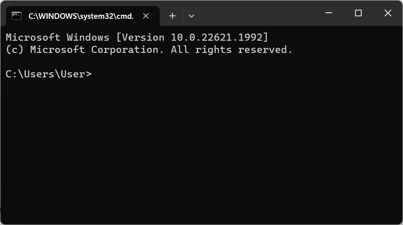
In command prompt type
python --version
or
python3 --version
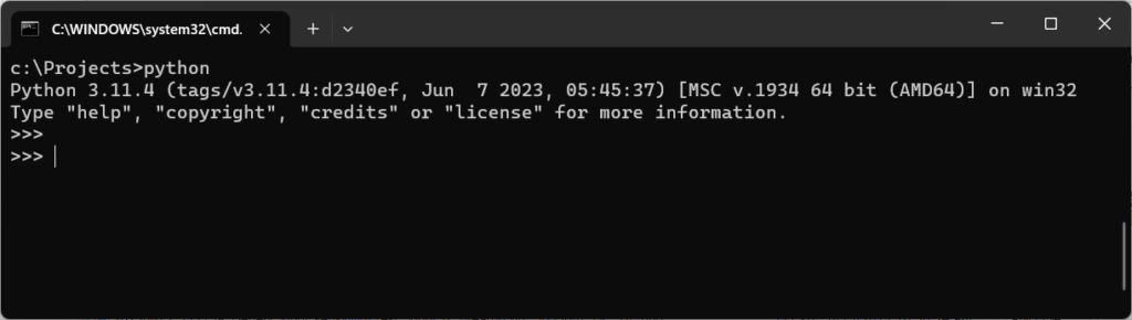
followed by Enter to check if python is correctly installed. You should get response indicating installed python version, like this:
Python 3.11.4
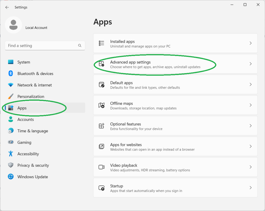
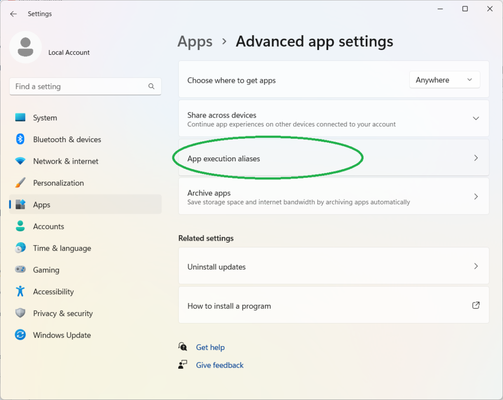
On Windows, if Microsoft Store is open when you execute “python” command or the command simply gives no response:
On Windows 11 go to Start Menu → Settings → Apps → Advanced app settings → App execution aliases and disable “python” and “python3” aliases.

On Windows 10 open Start Menu → Settings (“Gear” icon) → Applications → Applications and functions → Link “Application execution aliases”. Disable “python” and “python3” items.
PyVISA library installation
Open source PyVISA library can be used for interaction with NI VISA software which, in turn, provides functionality required to support communication with measurement instruments using protocols such as HiSLIP.
To install PyVisa library open command prompt and type:
pip install pyvisa
If you receive error message saying “'pip' is not recognized as an internal or external command, operable program or batch file.“, then ensure that Python is correctly installed.
Check if communication with Pendulum CNT-104S device is possible from python (at the very basic level):
- Ensure your instrument is connected to the network.
- Start Python in interactive mode by typing in command prompt:
python
- In python command prompt type the following lines replacing
192.168.0.25with the actual IP address of your instrument (can be checked in Settings → User options → Network → Ethernet IP address):
import pyvisa as visa rm = visa.ResourceManager() instr = rm.open_resource('TCPIP::192.168.0.25::hislip0::INSTR') instr.query('*IDN?')
The last line executes “*IDN?” query which asks the instrument for identification information. You should get response from the instrument like this:
'Pendulum, CNT-104S, 607017, v1.2.0 2023-07-13\n'
- Type the following to disconnect from the instrument and exit python:
instr.close() quit()
Examples
More complex scenarios imply using Python in non-interactive mode.
Here is an example showing very basic usage of python programming language to control the instrument.
#!/usr/bin/env python

# REPLACE WITH THE IP ADDRESS OR YOUR INSTRUMENT!
# (See Settings -> Settings -> User options -> Network -> Ethernet IP address)
INSTRUMENT_IP = '192.168.0.25'

import pyvisa as visa

rm = visa.ResourceManager()

def example(resource_str):
instr = rm.open_resource(resource_str)  # Connect to the instrument
instr.timeout = 5000  # VISA I/O operations timeout, in milliseconds

idn = instr.query('*IDN?')  # Send '*IDN?' and read response.
print('Running example 1 with {} at {}'.format(idn.strip(), resource_str))
print('In this example frequency measurement is performed on input A')

instr.write('*RST;*CLS')  # Reset to default settings, clear error and message queues.
# Configure the measurement: simple frequency measurement, with timeout.
# (Pay attention to double and single quotes)
instr.write(':SYSTEM:CONFIGURE "Function=Frequency A; SampleCount=10; SampleInterval=0.01; '
            'Timeout=On; TimeoutTime=1.0"')
# It's a good practice to check for errors.
err = instr.query(':SYST:ERR?')
if err.strip() != '0,"No error"':
    raise Exception('Error configuring measurement: {}'.format(err))

instr.write(':INIT')

# Waiting (in a blocking manner) for measurement completion.
# *OPC? query responds back only when all pending operations (measurement in this case) are completed.
# Measurement will be complete when all requested samples are collected or if timeout occurs.
instr.query('*OPC?')  # No need to use response here, because it is always '1' by SCPI standard.

data_str = instr.query(':FETCH:ARRAY? MAX, A')  # Will return a string of comma-separated numbers
data_str = data_str.strip()  # to remove \n at the end
if len(data_str) > 0:
    data = list(map(float, data_str.split(',')))  # Convert the string to python array
else:
    data = []

# Display measurement results
print('Results: {}'.format(data if data else 'no data (signal not connected?)'))
instr.close()

if name == 'main':
resource_str = 'TCPIP::{}::hislip0::INSTR'.format(INSTRUMENT_IP)
try:
example(resource_str)
except visa.VisaIOError as e:
print('Error occurred: {}'.format(e))