1. TECHNICAL DATA
1.1. Operating modes
- continuous,
- continuous with frame counting,
- burst,
- burst with waveform inversion,
- multiple burst,
- script (programmable burst and roll sequences),
- matrix (emulating a 4×4 part of a virtual matrix)
- forward/reverse direction (controlled by an external signal, low = reverse)
- halt indefinetly (controlled by an external signal, active low)
1.2. Outputs
- high-voltage output of generated waveforms (red BNC)
- low voltage waveform monitor output
- pulse-attached control bit (TTL level), each channel
- oscilloscope trigger pulse (TTL level, multiple trigger points possible)
- low-voltage superposition of two channels, inputs are made for high voltage
1.3. Inputs
- external clock (internally divided by 2)
- external trigger (active high)
- waveform direction
- halt waveform
1.4. Timing
resolution: max 12287 pulses of 3÷32767 clock units wide each (i.e. 15 bits resolution); every pulse may have different width
clocks: 20 MHz (crystal controlled, 1 time unit = 50 ns; default),
1 MHz (crystal controlled, 1 time unit = 1 μs),
≤1kHz (software controlled, adjustable in multiples of 1 ms), external.
pulse width: min 150ns (with 20 MHz internal clock)
1.5. Amplitude
max: ±100V, 185mA; other models: ±200V 120mA, ±400V 60mA
output impedance: ≤ 0.1 Ω
load: resistive || capacitive
slew rate: ca 400 V/μs at load ≤350pF
resolution: 12 bits (1 lsb = 50 mV in ±100V model)
accuracy: ±1LSB or ≤2% of setting, limited by settling time
Settled amplitude is independent on the load within the current limits.
1.6. Interface
serial (RS232), 57600 baud, 8bit, N, 1
1.7. Power supply
either 220/230V or 110/120V or 100V (factory setting), 50/60Hz, 160W
clean sinewave AC required (high voltage power supply contains a toroidal transformer)
1.8. Case
nVENT RatiopacPRO 19″ (3HE 84TE)
1.9. Computer
PC: Minimum requirements: any PC running Windows95 or above, including Windows 10, having a free serial port or USB-to-serial converter and a color monitor of at least 800×600 resolution.
Macintosh: Minimum requirements: any Macintosh with a serial port acting as “printer” or “modem” port, running MacOS 7 to 9 (including MacOS X in Classic mode) and at least 10Mb free RAM.
Software updates: Free download of all software for the waveform generator from the Company’s web site pendulum-instruments.com
2. SAFETY INSTRUCTION
2.1. Introduction
This instrument has been designed and tested for Measurement Category I, Pollution Degree 2, in accordance with EN/IEC 61010-1:2001 and CAN/CSA-C22.2 No. 61010-1-04 (including approval). It has been supplied in a safe condition.
Study this manual thoroughly to acquire ade- quate knowledge of the instrument, especially the section on Safety Precautions hereafter.
2.2. Safety Precautions
All equipment that can be connected to line power is a potential danger to life. Handling restrictions imposed on such equipment should be observed.
To ensure the correct and safe operation of the instrument, it is essential that you follow generally accepted safety procedures in addition to the safety precautions specified in this manual.
The instrument is designed to be used by trained personnel only. Removing the cover for repair, maintenance, and adjustment of the instrument must be done by qualified personnel who are aware of the hazards involved.
The warranty commitments are rendered void if unauthorized access to the interior of the instrument has taken place during the given warranty period.
2.2.1. Caution and Warning Statements
CAUTION: Shows where incorrect procedures can cause damage to, or destruction of equipment or other property.
The instrument cannot be powered from a DC-AC converter nor from a solid-state AC generator with non-sinusoidal output. It is recommended to monitor the output signal of the amplifier on the oscilloscope.
WARNING: Shows a potential danger that requires correct procedures or practices to prevent personal injury.
Red BNC contacts are high voltage outputs. Do not make/change connection during operation due to dangerous voltage levels.
High voltage outputs can only be connected to high voltage inputs on the summing modules, marked -IN and +IN, respectively. Never connect high voltage outputs to TTL inputs nor to each other.
Inside the WFG600 exist dangerously high voltage levels. Do not open the instrument!
2.2.2. If in Doubt about Safety
Whenever you suspect that it is unsafe to use the instrument, you must make it inoperative by doing the following:
- Disconnect the line cord
- Clearly mark the instrument to prevent its further operation

- Inform your Pendulum Instruments representative.
For example, the instrument is likely to be unsafe if it is visibly damaged.
2.3. Environmental Considerations
This section provides information about the environmental impact of the product.
2.3.1. Product End-of-Life Handling
Observe the following guidelines when recycling an instrument or component:
2.3.2. Equipment recycling
Production of this equipment required the extraction and use of natural resources. The equipment may contain substances that could be harmful to the environment or human health if improperly handled at the product’s end of life. To avoid release of such substances into the environment and to reduce the use of natural resources, we encourage you to recycle this product in an appropriate system that will ensure that most of the materials are reused or recycled appropriately.

3. WARRANTY
The Warranty Statement is part of the folder Important Information that is included with the shipment.
4. DECLARATION OF CONFORMITY
The complete text with formal statements concerning product identification, manufacturer and standards used for type testing is available on request.
5. QUICK START
More detailed exercises are described in the “Tutorial” chapter.
5.1. Follow these simple steps
- Turn on the computer and run the Waveform Generator program.
- Draw a few pulses. Click in the design window A or B. Note the pulse selection marker below the waveformsuperposition display at the top of the screen, and the active waveform mark (A and B buttons, to the left).
- Place an oscilloscope-trigger for easy synchronization with an oscilloscope. Select a pulse and press space key or use menu TIMING -> SET TRIGGER POINT.
- Turn on the waveform Generator. Connect the WFG600 to the mains and turn it on. The LED diodes will light on while the generator performs the self-check procedure and then they will all be turned off.
- The serial communication.
- PC: COMx (9-pin female D-SUB contact) and the waveform generator (9-pin male D-SUB contact).
- Important: Go to menu FILE->PREFERENCES and choose the communication port, the model of your waveform generator (WFG600) and communication speed (57600 baud). There you may also turn off the initial splash screen and define the file-saving behavior.
- Mac: Connect the serial communication cable between the “Printer” port and the WFG600 using the round mini-DIN plug; (for the software with letters “MP” use “modem” port)
- Connect an oscilloscope to the waveform generator. High-voltage outputs (OUT) require a 10:1 probe. Connect the synchronization output (TRG OUT) to the “external trigger” input in the oscilloscope. Set the scope trigger source to External, TTL level, Normal. It is recommended to use a probe also for the trigger signal.
- Initialize the communication. Establish a contact between the computer and the WFG600 (use menu OUT -> CONFIGURE CHANNELS… or press PC: control-T / Mac: T). The dialog with the list of installed output modules will be displayed. Click on pop-up menus to assign waveforms to the channels (a waveform may be assigned to more than one channel). Click on the RUN button. All waveforms will be downloaded and the generation will start.
- Play with the output signal
- Change pulse amplitude or width by clicking on it and dragging with the mouse. Observe how the generator follows the changes.
- Change a pulse width by dragging a marker on the time axis or (on PC) use the right-click to drag the pulse width.
- Change the amplitude of the whole waveform using Amax and Bmax controls at the righthand side of the screen.
- Change the waveform frequency using the timing control at the bottom-right. The display shows the width of the selected pulse. The remaining pulses are scaled proportionally.
- Click on the icon next to the timing control. Its picture changes from “waveform” to a single “pulse”. The width control applies now the selected pulse only.
- End the signal generation. Use menu OUT -> STOP or click on STOP button in order to stop the generator. When the data is loaded to the generator, it can be started simply by clicking on RUN button or using menu OUT -> RUN.
- More advanced functions or described in the Tutorial Chapter.
6. TROUBLESHOOTING
6.1. Run self-test
- Press and keep the RESET button on the generator.
- Observe the LED diodes. The six LEDs in the control module should light on and none in the other modules.
- Release the RESET button.
- Observe the LED diodes. LED diodes on all modules will sequentially blink and then all LEDs should be off. This means that the generator has successfully performed the self-test and is ready for operation.
- If this test fails – contact the manufacturer.
6.2. Red ERROR LED is on
- There was a communication error, probably caused by an unexpected command sent to the generator. It may occur if the generator was reset and the computer program was not notified. Execute OUT->CONFIGURE CHANNELS command to cancel the error. If the problem persists reset the generator and invoke the OUT->DISCONNECT command.
- If you always get an error then check the communications speed. You need a software communicating at 57600 baud. Older instruments require 19200 baud.
- Do not forget to Select the baud rate in FILE->PREFERENCES.
- If the error occurs in response to a certain function in the software you might need a firmware update. Please contact Pendulum Instruments.
6.3. “TIME OUT” message when trying to communicate
- Observe the blue “COM” LED on the control panel while executing OUT->CONFIGURE CHANNELS command – it should briefly light on. If there is no light blink – check the cable and port connections.
The new WFG600 uses a PC-standard modem cable pinout. A standard straight serial cable can be used here.
The WFG400 and some older versions of WFG500 used a Macintosh-standard printer cable pinout. Two cables were supplied with the instrument. Please use the supplied serial communication cable since a standard PC cable will not work.
If you use USB-to-serial converter please check the port number that was assigned and select it in the “Preferences” dialog (Windows computers).
If uncertain please contact Pendulum Instruments (send email to service@pendulum-instruments.com).
Mac: Change the serial port. The software rev 5.x is compiled for the “printer” port (the one with a printer symbol) as standard, and the software with suffix MP was compiled for the “modem” port (the one with a telephone symbol). Software rev 4.x (for WFG400) was compiled for the modem port.
USB-Mac: Newer Macintosh models do not have serial ports and an USB-serial converter or a serial port card has to be used (for example a Keyspan SXpro card). Typically, the Port#1 emulates the Mac printer port. If uncertain consult your Mac dealer or FLC Electronics AB.
- “Time out” may also occur when running a very slow waveform since the system waits for the waveform to end. Confirm the “Keep waiting?” dialog to continue or press RESET button on the WFG600 to abort and reset the generator.
6.4. No channels exist in configuration dialog
- The communication speed is wrong. WFG400 communicates at 19200 baud; WFG500 and WFG600 at 57600 baud. Use a proper version of the software.
- Check if correct baud rate is selected in FILE->PREFERENCES.
6.5. “Serial port occupied” message
- (Mac only) Check AppleTalk and Modem settings in the Control Panels. On PowerBooks with only one serial connection turn the AppleTalk off. On USB Mac check the control panel of the serial adapter.
6.6. Error LED while executing a command
If the problem repeats at the same place use older revision of the software, as it might use commands not supported in the waveform generator hardware (WFG600 is constantly expanding). Contact Pendulum Instruments for advice.
6.7. Still wrong …
- Restart the computer and reset the generator (as usual in such cases).
- Define the problem and send email to Pendulum Instruments, service@penduluminstruments. com.
6.8. Feedback
- Please inform us also if you discover bugs in the program, dislike any part of its behavior or wish to have some additional features.
- Do not hesitate to contact us if you have any questions or suggestions concerning the program or the instrument itself.
7. FRONT PANEL CONNECTIONS
7.1. Controller module
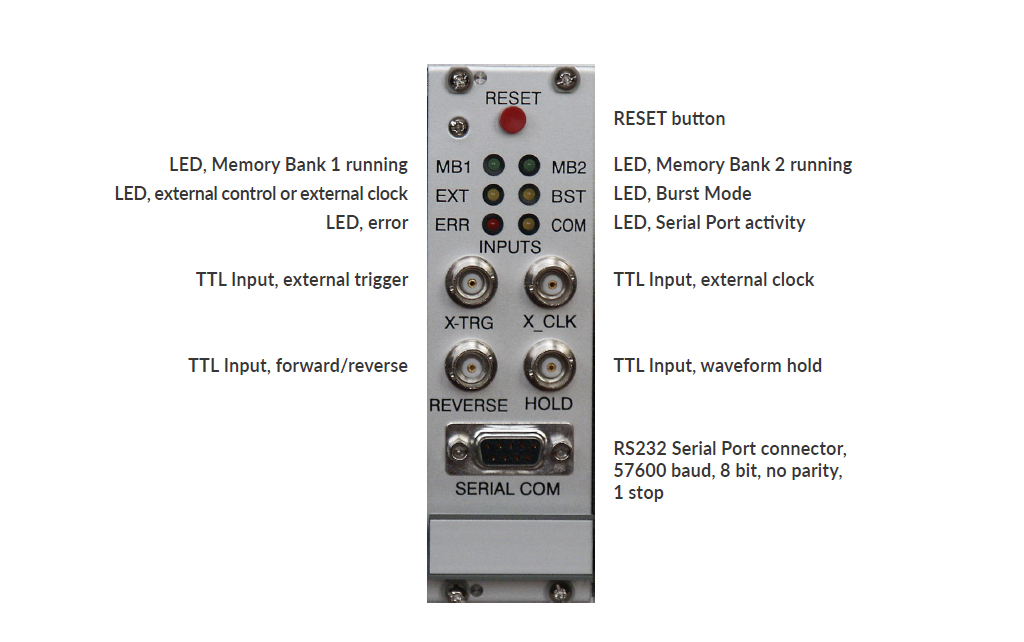
The “TTL Inputs” accept a TTL-compatible signal with amplitude between 0 and +5V, i.e. logic LOW and HIGH . Do not apply any negative voltage!
External trigger: After choosing menu OUT->External triggering a LOW level at this input will perform command “Run” while HIGH level (default) will execute the “STOP” command. LOW level may be achieved by simply shorting the input to ground.
External clock: A square wave, no minimum frequency. Observe the output to establish the max frequency.
Forward/Reverse: A LOW level (for example shorting to ground) will immediately reverse the direction of the waveform scanning. Provide a clean, debounced signal. (New in WFG600)
Hold: A LOW level at this input will hold the current amplitudes at all outputs until released. (New in WFG600)
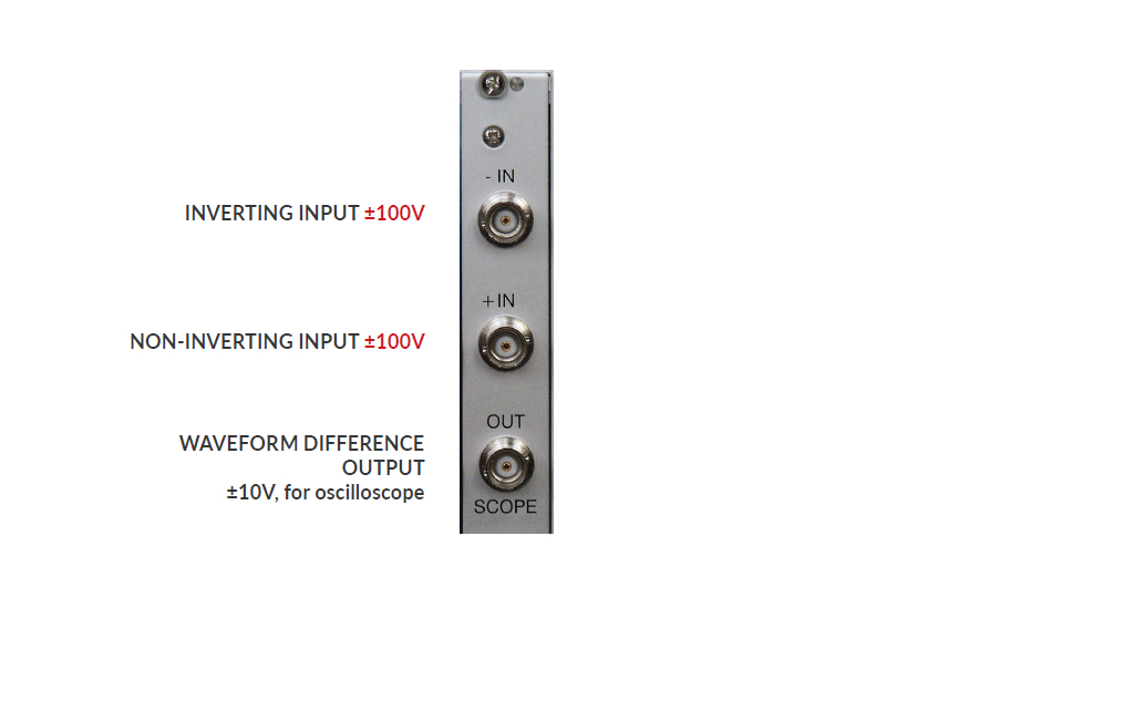
7.2. Summing module
7.3. Timer module / Output channels
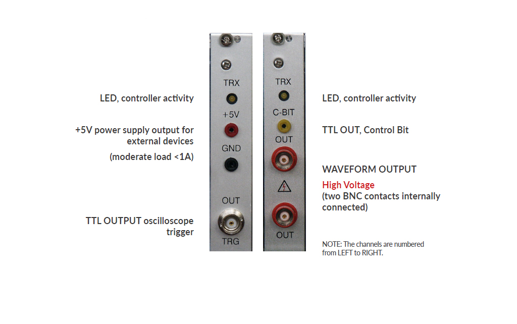
The channels are numbered from LEFT to RIGHT.
8. CIRCUIT DESCRIPTION
8.1. Introduction
The Waveform Generator has its origin in the research work on liquid crystals. It is thus optimized to produce, simultaneously in many channels, trains of pulses, each having its own duration, polarity and amplitude value. Typical arbitrary waveform generators are not well suited to this task since they were designed with quite different application in mind – generation of advanced analog functions, usually in one channel and at low voltage. Frequency and amplitude of such signals may be changed easily, but there is no easy and safe (for the connected device) way to alter the pulse trains during operation.
The generator has 8 channels and a common time base. The minimum pulse width is 150ns and the maximum amplitude is ±100 volts. The resolutions are 50ns and 50mV, respectively. The generator is controlled by a PC-Windows computer or Macintosh (OS9), taking advantage of the user-friendly operating system.
The waveform generator has the ability to change the applied waveforms during operation without transients. It has been accomplished by the use of two memory banks.
Mathematical relations between pulses in the waveforms and between different time-steps can be programmed-in to avoid repeated, manual adjustments of many pulses each time the waveforms should be altered. The waveforms may also be grouped for simultaneous amplitude adjustments, as for example, row and column electrodes in a matrix display.
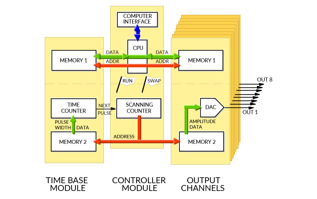
8.2. General Concept
Undisturbed waveform modification during operation is based on the incorporation of two memory sets. When the data from one memory set are used for the waveform synthesis, the other memory set can be freely updated. After successful updating, the memory sets are interchanged (swapped) immediately after completing the generation of the old waveform.
It is, thus, possible to consider the waveform generator as consisting of two, fairly independent, parts: a microprocessor system associated with one memory set and a hardware- controlled waveform-synthesis circuitry (Figure 1). Here, the second memory set is scanned by an address counter at a rate defined by the timing module. Obtained data are then transformed into a corresponding voltage level by a digital-to-analog converter (DAC) and a series of operational amplifiers.
Waveforms are not synthesized from equidistant points. Instead, there is a 15-bit width data associated with each individual pulse number. In other words – each time slot can have individual width.
8.3. Controller Module
The central device in the controller module is a Motorola 68HC11F1CFN4 microprocessor. It communicates with the host computer by a standard serial port. Received commands and data are used to update the currently associated memory on the designated module (or modules). They are also stored in own “note-pad” memory, since identical updating must later be performed on the other memory set in order to bring both sets to identical state.
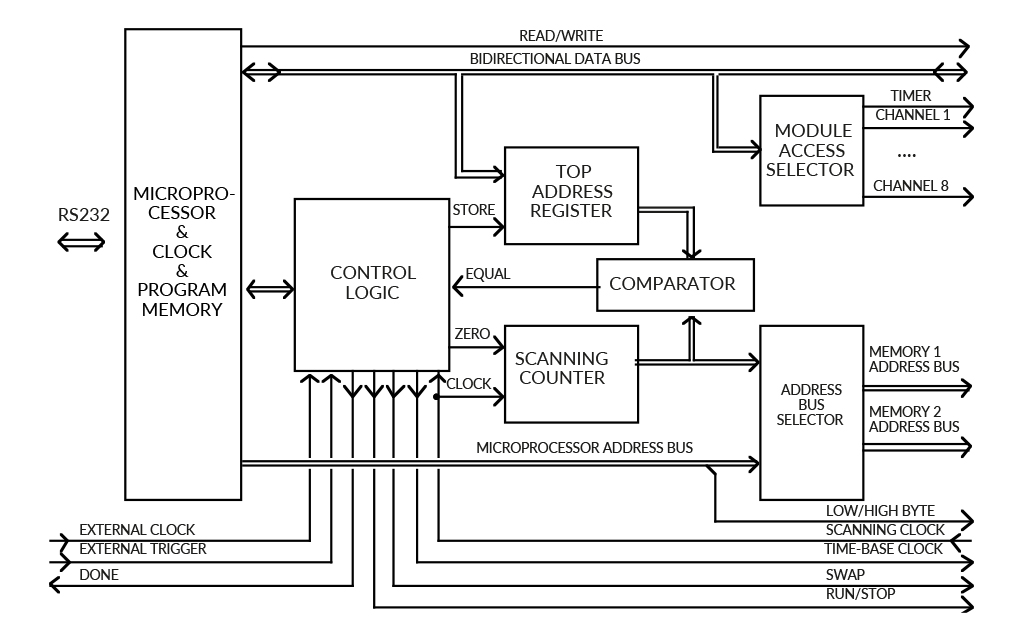
Both memory sets have separate address busses. The address-bus selector block connects one of them to the microprocessor’s address bus and the other to the scanning counter. The ‘memory swapping’ is performed by interchanging the above address bus assignments and forcing the modules to make corresponding change in their data-selector blocks. Swapping does not cause any delay.
The relation between the microprocessor address lines and the address inputs of the memory circuits is not straightforward. The microprocessor’s lowest address line, A0, is used as ‘Low/High-Byte’ control signal, which activates one of the two memory circuits. The memories’ address inputs are, thus, shifted up by one bit, and the RAM_A0 inputs are connected to the microprocessor’s A1 line, RAM_A1 to A2, and so on. Since the memories on all modules occupy the same address space, the microprocessor has to use the module-access selector functional block to aid choosing the desired memory circuit to communicate with. The specific memory circuit is, thus, chosen by three signals: module-select (the board), swap (the memory set) and low/high byte (the circuit). The data may be written into a few modules at once, if so desired.
While one memory set is associated with the microprocessor, the second one gets its addresses from the scanning counter, which counts from zero upwards (unless REVERSE direction is activated). The counter is driven by the scanning clock delivered from the timing module. The value, generated by the scanning counter, is compared with the address of the last waveform-pulse data, stored in a top address register. When the end of the waveform is reached, the comparator sends the ‘equal’ signal to the control logic block, which, in turn, checks if the microprocessor flags out for memory swapping or for terminating the waveform generation. If the memory swap is requested, then the ‘swap’ control-signal is inverted and the top address register is updated to the prepared value (because the waveform length might have been changed). The counter is then reset to zero and the new scan begins.
The control-logic block takes also care of some additional functions. It prepares the time-base clock, senses the external start-signal (if enabled), and supervises the operating mode, which may be either continuous, burst (i.e. the waveforms are generated once only) or other special modes.
8.4. Timer
The duration of each pulse is defined by a timing module (Figure 3). Here, a 15-bit data is loaded to a down-counter at the beginning of each waveform step. The counter is driven by a time-base clock, the speed of which is selectable and may be 1 or 20 Mhz (crystal controlled), a slower, software-controlled clock (in 1 ms steps) or an externally supplied one (should be less than 20 MHz but can be very slow). The output of this counter produces a scanning clock, which, in turn, advances a memory-address counter.
The 16th data bit contains arbitrarily placed trigger information, used to synchronize an oscilloscope (or other device) with the desired step of the waveform.
8.5. Data Memories
The part of the block scheme from Figure 3, enclosed in the dashed rectangle, is present both in the timing module and all analog-output modules. It consists of the memories, buffers, a data selector and a control logic, and its purpose is to deliver 16-bit data to the counter or, in the case of the analog-output channel, to the DAC.
Since the microprocessor operates on 8-bit data bytes, a conversion to the required 16-bit data words is needed. Thus, each memory set consists of two 8k*8 random-access memories, which store the lower and upper byte of the 16-bit data word, respectively. The memories are tied to the microprocessor data bus through a programmable logic device (CPLD). Normally, the buffers of the CPLD are in the high-impedance state (disabled), effectively disconnecting the memories from the data bus. When a specific memory circuit is selected by the microprocessor (in the previously described way), the control logic activates the corresponding buffer. The direction of data flow is then defined by the microprocessor’s read/ write signal.
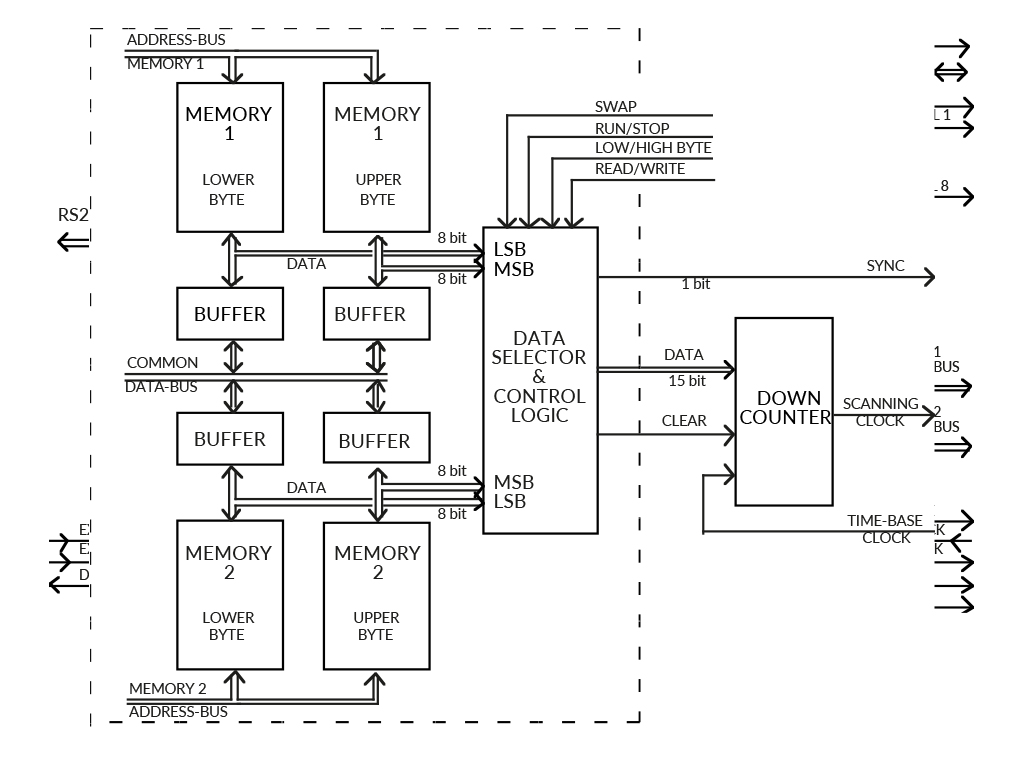
The buffers associated with the memory set being scanned are always disabled. The memories are, thus, isolated from the microprocessor activity and the data may be delivered undisturbed through the data selector to the DAC.
8.6. Digital-to-Analog Conversion
The process of conversion of binary data into the analog signal is crucial for the obtainable speed and amplitude. We use a 14-bit digital-to-analog converter DAC904U settling within 30 ns. The current output from the DAC is converted to a voltage by a fast operational amplifier OPA690. This signal is fed to a high-voltage amplifier PA98.
The DAC uses twelve bits (b11…0) out of sixteen data bits available, that gives 50 mV resolution of the pulse amplitude at the high voltage output. The sixteenth bit (b15) may be set via software and is provided as TTL-level output on the front panel. It may be used for other purposes, like controlling external devices.
Two isolated BNC contacts for high voltage (±100V) output are provided on the front panel of each module, since one usually connects both the load and the oscilloscope probe to the same signal. If the load is connected between two outputs (as in the case of a liquid crystal cell) one needs to monitor the difference between the two applied signals. For this purpose two summation modules are provided. The summation module has one inverting (-IN) and one non-inverting (+IN) inputs which can accommodate the ±100V signals from high-voltage outputs of the generator. The output of the summation module is low voltage in the range ±10V, low power and intended for oscilloscope only.
8.7. Programmable Logic Design
All digital logic is incorporated into programmable logic devices – CPLDs from Lattice.
8.8. Options
The generator is controlled through a standard serial interface and different computers or programs may be used in order to adapt the system to specific requirements. The communication protocol and commands are described at the end of this manual. This allows also to control the generator using LabView or similar software. It is advisable to contact Pendulum Instruments for the latest listing before programing a dedicated driver. Do not hesitate to contact the company when specific needs arise as it may be possible to adapt the software or hardware of the generator.
9. THE SOFTWARE
9.1. Overview
The software has initially been written for Macintosh computer and then translated to the PC- Windows environment. It has its origin in the liquid crystal research. The waveform generator is designed to be as straightforward to work with as possible, but containing all the features we found helpful in addressing of liquid crystal displays.
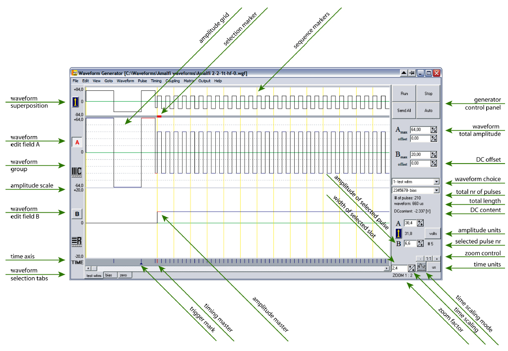
The snapshot of the Windows screen indicates the important functional parts of the program. Macintosh screen is analogous and can be seen in the Tutorial Chapter of this manual. Two waveforms (marked A and B, respectively) may simultaneously be designed, since we are usually interested in the relation between row and column signals. For the same reason, the superposition of these two waveforms (A-B or B-A), corresponding to the effective driving voltage seen by the liquid crystal cell, is presented for the reference (in a quarter scale) on the upper part of the screen. The optional, thin vertical lines mark here the line addressing periods. The waveforms, to be displayed on the screen, are chosen via ‘pop-up’ menus. The text on the menu button consists of the associated output-channel number and the waveform name
The pulses may be created or altered either by the usual ‘point, click and drag’ method (cursor) or by entering the desired value from the keyboard. A grid may be defined to facilitate the editing operation.
The timing information is drawn in the lower part of the screen. Short vertical lines mark the time-slots. The widths of the pulses may be altered in the same way as their amplitudes.
Additionally, the boundary between two time-slots may be moved. An arbitrarily placed oscilloscope trigger signal, marked as a small triangle, is also visible here. Since the waveforms are normally much longer than the available window size, a scroll bar is provided at the bottom of the window. The Goto menu assists in finding the desired waveform step.
Pulses, sequences and entire waveforms may be copied, cut, pasted, cleared, deleted and duplicated in the usual way. They may also be inverted, mirrored or rolled. The last editing operation can be undone. The commands affect the selected pulse or waveform. In the example presented, waveform A is active, which is marked by a frame around the ‘A’ letter. The pulse selection is visualized by a thick red line (on Mac: by an animated ‘marching ants’ pattern). Parameters of the selected waveform-step are displayed in the bottom-right part of the screen. The units are selectable via pop-up menus (volts, respective μs, or ±100 arbitrary units). The maximum-amplitude controls for respective waveform are drawn above the waveform names. ‘Clicking’ with the mouse on an up or down arrow makes an expected change, while clicking on the value allows for the keyboard entry. The timing may be changed in a similar way. The DC-content in the effective driving signal is continuously monitored.
The waveforms may be joined as column, row or arbitrary groups (called in the program as C, R, X, Y and Z-groups, respectively). Adjusting the maximum amplitude of a waveform assigned to a group, results in the corresponding adjustment in the remaining waveforms. It is, thus, possible to simultaneously change the amplitude of all column waveforms.
Three buttons for communication with the generator (‘Run’, ‘Stop’ and ‘Send all’) are placed in the upper-right corner of the screen. The fourth ‘Auto’/’Manual’ button controls the way the generated waveforms are updated. The default setting is ‘Auto’ which means that all changes are immediately followed by the generator. If more extensive alternations of the waveforms have to be done, the communication may be switched to a manual mode (then the ‘Send all’- button changes to ‘Update now’). Prior to using any of these buttons, the communication with the generator must be established and the waveforms assigned to physical channels of the generator, using a ‘dialog window’ where only the existing channels are shown.
The pull-down menus, shown in the menu-bar at the top of the screen, provide many additional features. The ‘Coupling’ menu requires special attention. It allows for defining the relations between pulses in the waveforms. The coupled pulses are presented by a distinct color when waveforms are drawn on the screen. Any number of pulses may have their amplitudes coupled together. This is done by choosing one of them as a ‘Master’ (for reference) and assigning the coupling parameters (master pulse name, multiplication factor ‘n’ and offset) to a ‘Slave’ pulse, so that its amplitude will always follow the relation:
Aslave = Amaster * factor + offset
When a ‘coupled’ pulse is altered, the software re-adjusts the amplitude of the master pulse and propagates the change to all related pulses, which may be in different waveforms, even those not shown on the screen. These slave pulses make then corresponding changes in their amplitude values. Finally, the appropriate information is transmitted to the waveform generator. There is no limit on the number of coupling chains nor on the number or placement of pulses within each chain.
The time-slots may be coupled together in the same way.
The number of waveforms is limited only by the available memory in the computer. The program has been written in object-oriented C (Symantec) for Macintosh, Borland Pascal for Windows3.x (revision 1.x) and Borland C++ for Windows95/98/NT/2000/ME/XP/ Vista/7/10 (from revision 2.0 up).