The Waveform Generator has its origin in the research work on liquid crystals. It is thus optimized to produce, simultaneously in many channels, trains of pulses, each having its own duration, polarity and amplitude value. Typical arbitrary waveform generators are not well suited to this task since they were designed with quite different application in mind - generation of advanced analog functions, usually in one channel and at low voltage. Frequency and amplitude of such signals may be changed easily, but there is no easy and safe (for the connected device) way to alter the pulse trains during operation.
The generator has 8 channels and a common time base. The minimum pulse width is 150ns and the maximum amplitude is ±100 volts. The resolutions are 50ns and 50mV, respectively. The generator is controlled by a PC-Windows computer or Macintosh (OS9), taking advantage of the user-friendly operating system.
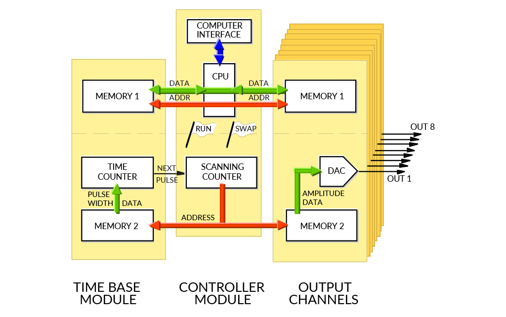
The waveform generator has the ability to change the applied waveforms during operation without transients. It has been accomplished by the use of two memory banks.
Mathematical relations between pulses in the waveforms and between different time-steps can be programmed-in to avoid repeated, manual adjustments of many pulses each time the waveforms should be altered. The waveforms may also be grouped for simultaneous amplitude adjustments, as for example, row and column electrodes in a matrix display.