1. COMPATIBILITY AND PLATFORM ISSUES
The toolbox is composed for use with LabVIEW version 6.0.2 and is now recompiled for LabVIEW version 8 compatible with present software revisions.
In order to take advantage of all the toolbox VIs you also need the core driver, you can install them together as one package. The VIs in the toolbox are backward compatible with the previous release, however those VIs that no longer serve any purpose or whose functionality has been taken over by the core driver have been removed.
The following were removed as they are no longer necessary:
- FLCWFG Build Timing String.vi
- FLCWFG Build Waveform String.vi
- FLCWFG End Data Transfer.vi
- FLCWFG Log Global.vi
- FLCWFG T-Data To Word.vi
- FLCWFG V-Data To Word.vi
- FLCWFG Write & Read.vi
- FLCWFG Write To Log.vi
- FLCWFG PREF_U.llb
The functions of the following VIs are available in the core driver:
- FLCWFG Burst and Invert All.vi (LCWFG500 Configure Clock.vi)
- FLCWFG Clock Setup.vi (LCWFG500 Configure Clock.vi)
- FLCWFG Close.vi (LCWFG500 Close.vi)
- FLCWFG Errorcode Interpretation.vi (LCWFG500 Error Message.vi)
- FLCWFG Initialize.vi (LCWFG500 Initialize.vi)
- FLCWFG Normal Burst.vi (LCWFG500 Configure Clock.vi)
- FLCWFG Ready Querry.vi (LCWFG500 Utility Ready Query.vi)
- FLCWFG Reset.vi (LCWFG500 Reset.vi)
- FLCWFG Run.vi (LCWFG500 Run.vi)
- FLCWFG Set Software Clock.vi (LCWFG500 Configure Clock.vi)
- FLCWFG Status Request.vi (LCWFG500 Status Request.vi)
- FLCWFG Stop.vi (LCWFG500 Stop.vi)
2. INSTALLATION OF THE DRIVER PACKAGE
First shut down LabVIEW if it is running.
If you have already installed the core driver, remove first all personal VIs that you have added to the folder LCWFG500 and store them in a safe place (e. g. move them to the user library, user.lib). Now delete the folder LCWFG500.
Proceed by copying or moving the folder LCWFG500 (which also contains the folder toolbox) to the instrument library (instr.lib) of your copy of LabVIEW.
If you so whish you can now move your personal VIs back to the folder FLCWFG500, however we recommend you do not store any personal VIs in the driver folder.
Once you restart LabVIEW a menu will be created in the instrument library pallet as well as all submenus.
Before you start working with the drivers for the first time, chose mass compile from the file menu and select the folder you just installed.
That’s all.
3. BASIC IDEA BEHIND THE DRIVER SET
Creating modular programs such as subvi’s is something entirely different from creating a stand alone program such as that delivered with your WFG 500. Extreme care has been taken to make all VIs robust but at the same time execution speed has been an important factor. The communication with the waveform generator is based on the VISA system.
As for handling the data in LabVIEW the best way to represent a waveform is in a two dimensional array. In this way one immediately avoids the chance that individual waveforms and timing contain different amounts of data. Another important issue is that one should work with the ‘real’ values, that is true times, e.g. microseconds, and true voltages. A number of VIs are included that perform conversion of the data to and from this format as well as VIs which provide easy tools to handle the data.
This version of the drivers does not yet support the use of couplings. When you import data from a file the couplings will be ignored.
4. GETTING STARTED
The first thing is to open the communication channel with the generator, that is initialize the LCWFG500 Initialize.vi and setting the appropriate parameters. The layout of a basic program is shown in the figure below.
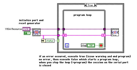
The error handler contains only ‘serious errors’ that means those that will endanger the communication. Most errors that occur during operation are soft-solved and will not interfere with your program, that is if you do not specifically want them to change your program flow.
After you have decided to quit the program you must close the VISA session of the serial port.
You can control more than one generator from the same LabVIEW program. All you have to do is initialize two (or more) serial ports and separate the operations with them.
5. IMPORTING DATA FROM FILES
The VI library contains a file filter FLCWFG File Filter.vi which extracts all relevant information from files created with the normal WFG programs on Mac and PC, however the current version does not extract the coupling data. Most users have no use for all of this information in a LabVIEW program, therefore a translator is provided, FLCWFG File Data Translator.vi that will create a cluster containing all necessary information for handling the waveforms. It is such a cluster which is “send ready”, that is all information to unambiguously send the data to the generator. As mentioned above, the best way to handle the real data is in a 2D array, FLCWFG Unmold Data.vi does just this starting from the full data cluster.
Once you have a 2D array you are ready to perform all sorts of operations on it. In addition to the data array, an array containing all trigger-bit and control-bit information with the same dimension as the data array is available as well as arrays containing the waveform names and there channel data and the time unit used for these waveforms, e.g. 0,1 μs for the 10 MHz clock.
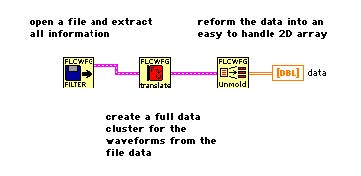
The data array is structured as rows, that is the first row (first index=0) contains the timing data in microseconds, all subsequent rows contain the voltage data of a waveform. The above layout of the data array makes it possible to access timing and individual waveforms subsequently by wiring it to a for loop. Should you wish to access a column of pulses simultaneously you can first transpose the array and then wire it to a for loop. To view the data in a graph use FLCWFG Build Graph Data.vi to obtain the correct LabVIEW format for graphs, set the graph to ‘square interpolation’ with the jump on the fist point (or copy it from the VI).
6. HANDLING WAVEFORM DATA
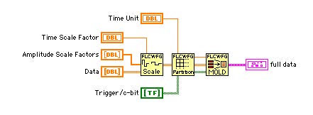
One of the major differences with working with the 2D arrays and the full data clusters is that the timing is in true values. We recommend that you use microseconds throughout your programs and convert appropriately when desired. In doing so one will encounter situations where a pulse as entered in the 2D array can no longer be represented by a single slot on the generator. As an example consider that you have selected the 10MHz clock and want to create a pulse of 5 ms that is 50000 clock units, then one needs to split this pulse into two slots. As a user you do not want to be bothered with this and hence FLCWFG Partition Raw data.vi does the job for you.
A situation as described above can appear quite easily when you scale timing data, which can be done with FLCWFG Scale Data.vi. This VI takes a set of scaling factors and changes the 2D data accordingly, but be sure to partition the data before you mold it back into a full data cluster which is needed for downloading operations.
7. LOADING WAVEFORMS INTO THE GENERATOR
Once you have composed a full data cluster ready to send, you use FLCWFG Download Wavefroms.vi to get them into the generator. Everything will be taken care of to get all information into the generator, including timing. An important part of the information is the assignment of the channels to which each waveform should be written. This is an array of integer elements of a size equal to the amount of waveforms. The integer itself is a translation of the bit pattern to a number. This means that you add powers of two to control the channels:
- 2 (binary 00000010) means channel 2,
- 3 (binary 00000011) means channel 1 and 2,
- 4 (binary 00000100) means only channel 3
- etc.
A lot can happen when you handle data and related information, therefore one should be careful when making changes. A dedicated VI is included to perform a standard check of the waveform cluster. FLCWFG Check Waveforms.vi will also warn you when actions have been taken to correct errors or will prompt you for setting the channel data.
If you already feel more comfortable, take a look at the vi LCWFG500 Send Data.vi which provides even more possibilities. The vi FLCWFG Download Waveforms.vi is based on this core driver vi.
As of LabVIEW version 6, National Instruments has introduced a new data type called VISA Resource Name, which replaces the VISA descriptor strings. When you insert such a control into a subvi, you can directly select the eligible port for communication. The figure below shows a call chain for initalizing, sending and closing.

For running and stopping the waveforms one just calls the subvi’s LWFG500 Run.vi and LCWG500 Stop.vi respectively.
Setting the clock is usually done during the download action when the VI decides from the time unit which clock should be set. You can change all the clock settings using the VI LCWFG500 Configure Clock.vi located in the core driver.
As a default the run mode is set to continuous and internal triggering, using the configure clock VI one can change the triggering or run mode.
8. APPLICATION EXAMPLES
8.1. FLCWFG Waveform Player.vi
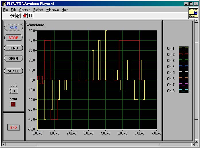
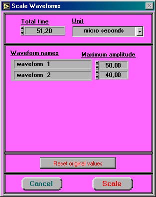
FLCWFG Waveform Player.vi is a program that enables you to open a file created with a normal WFG500 program (Mac or PC), send it to the generator, run it and rescale timing and waveform amplitudes.
8.2. FLCWFG Frequency Generator.vi
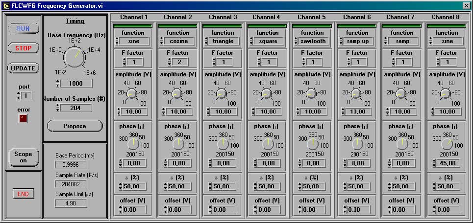
FLCWFG Frequency Generator.vi is a much more elaborate program. It simulates a frequency/phase generator using the WFG 500. Before it runs it checks which channels are available. You will see a green indicator above those channels. For each channel you can select the desired waveform such as sine, triangle, square etc. and its parameters. The frequency is set on the Timing panel together with the number of samples you wish to use. Keep in mind that larger amounts of samples not only take longer time to generate, but also to send. As all channels have a common time base, the frequency difference between them must be an integral number. You can set this using the frequency factor of each channel. Next, you can control all amplitudes separately, as well as the phase and offset. The duty cycle control works with the square wave only. A trigger point is set at the beginning of the base period. The button Propose will give you the best approximation of the desired timing. To send the information to the generator click the button Update. Should you want to see the data in a graph click Scope on.
8.3. FLCWFG Waveform Editor.vi
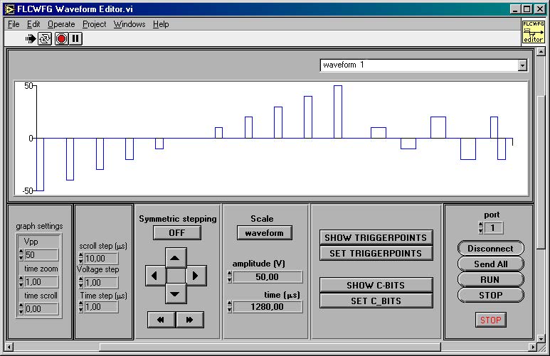
FLCWFG Waveform Editor.vi is a rather elaborate program. It allows for selecting pulses on a graph using a mouse. If you click a pulse it will be selected and show up red. If you click and drag you can select a range of pulses. When you hold down shift and then click a pulse you add the just selected pulse to the already existing selection, shift click drag adds a range of pulses. If you shift click an already selected pulse it will be removed from the selection. Clicking left from the voltage axis will deselect all. The amplitude and time controls contain the total time of the waveform and the maximum amplitude encountered in it if scale is set to “Waveform”. If you chose “selection” for scale, then the value of the first pulse in the selection will be visible. Changing anything in these two controls will immediately scale either the entire waveform or just the selection. To the left of the scaling section you find stepper control buttons. The individual step sizes are listed to the left of the stepper buttons and can be altered at your convenience. An extra option is included to allow for symmetric stepping, this is similar to scaling but will reduce or increase the amplitude by the step value. If this option is off, then the step value is just added or subtracted from the voltage data. To find the trigger positions click Show Trigger Points, to find c-bit positions in the current waveform click Show C-bits. To set the trigger points over the entire selection on the graph click Set Trigger Points, and similarly, if you which to set the c-bits click Set C-bits.
In order to send anything to the generator you must first connect to it, so click Connect. If you are connected, then the button shows Disconnect and the buttons Send All, Run and Stop are enabled. If this is not the case then an error has occurred during connecting. To end the program click Stop. Any changes you make will immediately be send to the generator, in this way you can easily optimize time and voltage settings for individual pulses.
Scroll the window left to find controls to change the graph settings; these include the maximum amplitude shown in the graph, the time zoom and the time scroll.
9. ALPHABETIC INDEX
9.1. FLCWFG Add At Index.vi

This vi will increment all data points at the index selection positions with the add step value. To select timing wire 0 to the “timing/waveform” control, another value represents the subsequent rows of waveforms in the data array. When the option “symmetric adding?” is true, the vi will add the step when the data is positive and subtract it when it is negative. This allows for setting the “amplitude” of the selected pulses as in a frequency generator, no additional offset will be created.
9.2. FLCWFG Assign Channels.vi

This vi opens a pop-up panel in which you must assign each available channel a waveform or action. The vi probes automatically which channels are available on the generator connected to the VISA reference.
The input array of strings “Waveform name(s)” is in principle unlimited. This means that you can not only pass the physical waveforms themselves, but also actions related to that string. The output “channel data” contains as much elements as the “waveform name(s)” input. If elements are added for actions, e.g. as is or set zero, this must be detected afterwards and these elements should be removed from the “channel data” before they are replaced in the waveform cluster.
The input “Channels” can be used to preload a choice of the channels. If the given channel array is non-unique (e.g. a channel is assigned twice or more) the last in order will be pre-loaded.
9.3. FLCWFG Build Graph Data.vi

This vi prepares the data in such a way that it can be displayed in an xy-graph. An extra (0,0) element is added to each waveform in order to be able to show the data in the graph in a correct manner. The interpolation style of the plot should be set to “squaring” with the transition on the first point (or just choose “create indicator” when you wire the output of this vi).
9.4. FLCWFG Build Picture Data.vi

Starting from the array “Data”, this vi will create the necessary output to create a plot of the waveforms such that it can be build up with line segments in a picture.
9.5. FLCWFG Clock Pop Up.vi

This vi is a pop up window that may be called to set the time unit. The “FLCWFG Waveform Check.vi” calls this window if the data contains an incorrect time unit.
9.6. FLCWFG Download Waveforms.vi

This vi uses the vis contained in the Core Library LCWFG500.llb to send the data to the waveform generator. The cluster full data contains all necessary information about waveforms and timing. What actually is sent to the generator can be controlled with the boolean array “Send?”. It should contain the number off wavefroms+1 elements. The first element of that array controls the timing. If an element is true the corresponding waveform (or timing) will be sent. If it is left unwired the timing and the first eight waveforms will be sent.
This vi actually translates functionality already available in the Core Library but is added here to ensure compatibility with previous posted beta-versions and examples therein.
9.7. FLCWFG File Data Translator.vi

This vi translates data obtained from a file to a convenient LabView cluster. This version (October 2000) does not yet contain the coupling data, it will be added as a separate cluster in a later version.
If the file indicates that the software clock must be used, the data in “reserved 1″ contains the time unit in microseconds [1000..35000]. If this is 0, a pop up window will appear prompting you to enter the value of the time unit.
9.8. FLCWFG File Export.vi

This vi exports a full data cluster to a wfg-file which can be read by the other programs. Data which is not relevant in LabView has been set to a default value. If you replace an existing file then all coupling data will be lost as the current version does not yet support couplings.
9.9. FLCWFG File Filter.vi

This vi opens and translates a file created with the FLC Electronics program for the WFG waveform generator. The output is a cluster containing all necessary data for reconstruction. Translation of the coupling data will be added in later versions.
9.10. FLCWFG Find Index by Time.vi

This vi finds the index (column in the array “Data”) of the pulse which is active at a given time.
9.11. FLCWFG Frequency generator.vi

This is an application program that simulates a frequency/phase generator.
9.12. FLCWFG Make Picture.vi

This vi constructs a picture of the supplied “Data” which may be viewed in a picture indicator. It also supplies “origin” and “scale” data which can be used for on-picture editing.
9.13. FLCWFG Mold Data.vi

This vi takes correct unitized and partitioned data and reshapes it into a full data cluster which can be used directly for sending to the generator. (use “FLCWFG Partion Raw Data.vi” to convert raw data into a suitable format for the WFG 500)
9.14. FLCWFG Mouse Position to VT.vi

This vi calculates from a set of inputs (such as the mouse pointer position in a picture, the origin of the axes system and the scale of the drawn waveform in a picture) what the time and the voltage level of the indicated point are inside the waveform.
9.15. FLCWFG Partition Raw Data.vi

This vi “partitions” raw data into a useful form for the FLCWFG 500. It creates slots with unitized timing values based on the “time unit” (in microseconds) input. This means that the data contains true time values in microseconds. The vi evaluates if extra slots need to be inserted to obtain the true time if the waveform is to be downloaded into the generator. If a slot would contain 1 unit it is automatically set to two units as this is the minimum requirement. If it would contain no unit (or set to zero time) it is simply erased from the data. The timing data is contained in the first row of the data array. All other rows represent individual waveforms by their voltage data.
9.16. FLCWFG Pop Up Time Unit.vi

This is a pop up window which queries the user to input a time unit for the software clock. It is called by “FLCWFG File Data Translator.vi”.
You should normally have no need to use this VI directly, as it is called by higher level VIs.
9.17. FLCWFG Scale At Index.vi

This vi will scale all data points at the index selection positions with the scale factor. To select timing wire 0 to the “timing/waveform” control, another value represent the subsequent rows of waveforms in the data array.
9.18. FLCWFG Scale Data.vi

This vi will scale data. It will scale time regardless of the clock setting and it can therefore deliver time data which is not executable with the current clock setting. Use “FLCWFG Partition Raw data.vi” to alleviate this problem using another clock setting. Also the voltage data may exceed 100 V which can not physically be produced by the WFG 500, values higher then 100 V amplitude will be sent as 100 V amplitude.
9.19. FLCWFG Scale Waveforms Pop Up.vi

This vi is used as a pop up window. The user can choose the scale settings at will starting from the current (TRUE!) maximum amplitudes of the waveforms and by the total time of the waveforms.
9.20. FLCWFG Set At Index.vi

This vi will set the trigger or c-bit in a trigger/c-bit data array at the selected indices of either timing or a waveform. If the option “add?” is true existing triggers will remain in the array, otherwise triggers will only be set at the index positions.
9.21. FLCWFG Unmold Data.vi

This vi takes data from a full data cluster (as obtained from the file translator) and transforms it into easy to use arrays in LabView. The data is contained in a two dimensional array with the first row the timing data in microseconds and all other rows representing the amplitude data of a waveform in volts. The same data layout is used in the array containing trigger/c-bit data.
9.22. FLCWFG Waveform Check.vi

This vi will perform a set of test to ensure that the waveforms make sense. Appropriate actions will be taken to correct errors.
IT IS RECOMENDED THAT YOU USE THIS VI EACH TIME BEFORE DOWNLOADING THE WAVEFORMS.
9.23. FLCWFG Waveform Editor.vi

This is an application example that enables you to make selections on a graph, scale and step values dynamically and set trigger or c-bit information.
9.24. FLCWFG Waveform Player.vi

This is an application example with which you can open a file, scale it and send it to the generator.