General information#
Revision 2
12NC 4031.602.21001
About this Manual
This manual contains directions for use that apply to the FTR-210R GNSS disciplined Frequency and Time References and targets Firmware release v1.5.9 and higher.
Warranty
The Warranty Statement is part of the folder Important Information that is included with the shipment.
Declaration of Conformity
The complete text with formal statements concerning product identification, manufacturer and standards used for certification type testing is available on request.
Preparation for Use#
Preface#
Introduction#
Congratulations on your choice of Measurement Instrument - FTR-210R GNSS disciplined Frequency and Time Reference.
The FTR-210R GNSS disciplined Frequency & Time Reference is a multi-output Frequency Standard, with close-to-Cesium stability, thanks to the GNSS control. There are 7 standard outputs (5x 10MHz, 1x 5MHz and 1x 1-pps) that can be expanded with up to 4 extra outputs, plus a programmable 100 MHz pulse output option. An optional input for frequency measurements to 400 MHz turns the FTR-210R into a one-box ultra-high performance frequency calibrator with up to 13 digits resolution in a second. The optional integrated independent frequency calibrator guarantees true traceability to GPS-time scale and NIST. Traceable calibration reports are easily generated.
The FTR-210R offers for example the following benefits:
GNSS controlled Rubidium atomic clock
Primary standard traceability option via built-in calibrator and generation of calibration reports
Optional Frequency measurement input to 400 MHz with ultra-high resolution (up to 13 digits/s)
Graphical intuitive User Interface, with large 5” color touch-screen control
Web server functionality ensures Control and Monitor from anywhere in the world via Ethernet.
Up to 9x 10 MHz outputs
1x 5 MHz and 5x 10 MHz ultra-stable frequency reference outputs as standard
Optional outputs include: 4x10 MHz, 4x1-pps, or 0.1, 1, 5, 10 MHz
Optional programmable pulse output 0.5 to 100 MHz
Integrated 1Gbit Ethernet interface with SCPI commands support
Design Innovations#
Frequency and/or Time standard#
When used as a GNSS disciplined Frequency standard, the short-term stability is very high, and ageing is virtually zero. When used as a stand-alone Frequency standard, in manual holdover mode, the stability is ultra-high. Ageing is less than 5E-11/month. When used as a GNSS disciplined Time standard, the 1-pps time reference output, differs less than 10 ns rms from the GNSS receiver. When GNSS disciplining is removed, the hold-over drift is very low: typically 1 μs/24h.
Disciplined Mode The frequency deviation between the local oscillator and the received GPS-signal is used to continuously adjust the oscillator. The resulting 1 h and 24 h mean freq. and phase offsets are displayed continuously on the front panel (if traceability option is installed).
Hold-Over Mode The internal timebase oscillator is not adjusted. This mode is normally automatically entered when there is no usable received GNSS-signal. This mode can also be activated via the Manual Hold-over setting. If there is a valid received GNSS signal, the actual frequency offset and phase offset are calculated and displayed (if traceability option is installed).
Modular, multi-output configuration#
The basic configuration contains 5x 10MHz, 1x 5MHz, and 1x 1-pps outputs, to support other instruments, testers, or test objects. If that is not sufficient, 4 additional outputs can be fitted on the rear panel. These outputs are either
4x 10 MHz
4x 1-pps
0.1, 1, 5, and 10 MHz
Additionally you can enable an optional programmable pulse output, 0.5 Hz to 100 MHz, via a SW license, at any time.
Measurement input for one-box frequency calibration#
The ultra-stable frequency reference, combined with the optional DC to 400 MHz measurement input, converts the FTR-210R Frequency Reference to a complete one-box frequency calibrator, at any time via a SW license.
Measurement functions include Frequency and Period Average. TIE (Time Interval Error) and Frequency Offset are optional functions (SW enabled).
The performance of the measurement input is state-of-the art. You have 14 ps time resolution (7 ps optional) and up to 12 - 13 digits of frequency resolution for 1s gate time. Measurements are gap-free, meaning all individual cycles are counted without any gap.
You can follow short-term and long-term stability of the device under test on the 5” color display, both numerically and graphically. The measurement rate can be set from 1 MSa/s (20M Sa/s optional) down to one sample every 1000 s.
You can store up to 32M measurement samples in each session, and store up to 1G measurements in a non-volatile memory.
The FTR-210R can produce traceable calibration protocols in CSV format of both the internal timebase reference (optional), and the device under test, at any time.
Unique Traceable Frequency Standard for the calibration lab#
Off-air frequency standards have existed for decades. But they all have had the same internal architecture (Fig. 1). The unit is, in effect, a “black box”, with an antenna input and a frequency output. The local oscillator’s control process (disciplining) is hidden from the user. Typically, users have used another frequency reference, a timer/counter and a PC for logging the deviation between the “black box” and the external frequency reference.
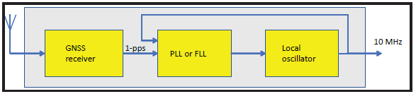
Fig. 1 A typical “black box” GPS-receiver (antenna in - reference out). Internal oscillator off set and adjustments are invisible to the user.#
The concept of traceability requires an unbroken chain of comparisons to international standards, on a continuing basis, where all comparisons produce documented results with stated uncertainty. The option 220 in FTR-210R is a documenting frequency comparator/calibrator that is independent from the disciplining process. The received GNSS signal is continuously and gap-free measured against the local oscillator. Phase and frequency deviations are stored internally and can at anytime be transferred to any PC, via the Ethernet interface, to almost anywhere in the world. Alternatively, this data can also be copied to a USB stick.
A traceability record for print-out can be obtained. The unbroken calibration history chain — day by day — is maintained in the non-volatile memory for several years, with the current mean offsets being displayed continuously on the front panel color display.
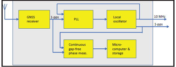
Fig. 2 FTR-210R has built-in continuous comparison between the GNSS receiver and the internal oscillator. The frequency offset is displayed and stored and a traceable calibration protocol can be produced at any time.#
Such unique traceability to primary standards means that the FTR-210R never needs to be sent away for traceable re-calibration. Thanks to this design, the very high stability built-in rubidium oscillator is continuously calibrated to the primary time and frequency standards.
Powerful and easy-to-use calibration tools#
The optional measurement input converts FTR-210R to a-box Frequency Calibrator. Using the MATH function or dedicated Frequency Offset measurement function (Option 152F, SW enabled), the Frequency of the device under test can be displayed either as absolute frequency, e.g. “10.000 000 01 MHz”, or as deviation from nominal frequency, e.g. “10 mHz”, or as relative deviation e.g. “1E-9”.
Setting limits for calibration tolerance, with clear pass/fail indicators, further eases the manual or semi-automatic calibration.
Full flexibility for local or remote control#
The FTR-210R is operated manually on the bench via the 5” graphical touch-screen display. You can also connect a mouse, wired or wireless, to one of the front panel USB ports for easier operation.
The FTR-210R comes as standard with a Gbit Ethernet interface for remote control and data transfer. Using a Wi-Fi dongle in the front panel USB port, enables you to connect FTR-210R to your local wireless network.
You can access and control the instrument from your lab bench, or from anywhere in the world, using the integrated web server interface function.
Safety#
Introduction#
Please take a few minutes to read through this part of the introductory chapter carefully before plugging the line connector into the wall outlet.
This instrument has been designed and tested for Measurement Category I, Pollution Degree 2, in accordance with EN 61010-1:2011, and CSA C22.2 No 61010-1-12 (including approval). It has been supplied in a safe condition. Study this manual thoroughly to acquire adequate knowledge of the instrument, especially the section on Safety Precautions hereafter and the section Installation.
Safety Precautions#
All equipment that can be connected to line power is a potential danger to life. Handling restrictions imposed on such equipment should be observed.
To ensure the correct and safe operation of the instrument, it is essential that you follow generally accepted safety procedures in addition to the safety precautions specified in this manual.
The instrument is designed to be used by trained personnel only.
Serviceable parts#
There are no parts or components inside the instrument that are serviceable by user.
Removing the cover for repair, maintenance, and adjustment of the instrument must be done by qualified personnel who are aware of the hazards involved.
The warranty commitments are rendered void if unauthorized access to the interior of the instrument has taken place during the given warranty period.
To prevent electrical shock or damage to the device, do not insert foreign objects into any openings or ports except as explicitly instructed in this User Manual for the intended replacement of parts or the installation of approved accessories.
Caution and Warning Statements#
Caution
Shows where incorrect procedures can cause damage to, or destruction of equipment or other property.
Warning
Shows a potential danger that requires correct procedures or practices to prevent personal injury.
Symbols#
Several symbols are depicted on various parts of the instrument.
|
Shows where the protective ground terminal is connected inside the instrument. Never remove or loosen this screw. |

Grounding faults in the line voltage supply will make any instrument connected to it dangerous. Before connecting any unit to the power line, you must make sure that the protective ground functions correctly. Only then can a unit be connected to the power line and only by using a three-wire line cord. No other method of grounding is permitted. Extension cords must always have a protective ground conductor.
Caution
If a unit is moved from a cold to a warm environment, condensation may cause a shock hazard. Ensure, therefore, that the grounding requirements are strictly met.
Warning
Never interrupt the grounding cord. Any interruption of the protective ground connection inside or outside the instrument or disconnection of the protective ground terminal is likely to make the instrument dangerous.
|
This symbol is used for identifying the chassis terminal. It is always connected to the instrument chassis. |
|
Caution, risk of danger. User manual must be consulted when any action is made with any connector/terminal which this symbol refers to, in order to find out the nature of the potential hazards and any actions which have to be taken to avoid them. |


Personal safety is ensured when the input signal level is below 30 Vrms (when accidentally touching the input signal lead)
Damage level for the input decreases from 350 Vp to 12Vrms when you switch the input impedance from 1 MΩ to 50 Ω.
Measurement BNC cables length shall be kept below 3m.
Circuits of external devices connected to BNC sockets, USB and Ethernet sockets must be separated from the power supply network (and from other sources of dangerous voltage) at the level of reinforced insulation. This separation should not be confused with the permissible voltage of the external signal, including the voltage of 350 Vp referred to in the manual. If the equipment is used in a manner not specified by the manufacturer, the protection provided by the equipment may be impaired.
Fuse
The secondary supply voltages are electronically protected against overload or short circuit. The primary line voltage side is protected by a fuse located on the power supply unit. The fuse rating covers the full voltage range. Consequently, there is no need for the user to replace the fuse under any operating conditions, nor is it accessible from the outside.
Caution
If this fuse is blown, it is likely that the power supply is badly damaged. Do not replace the fuse. Send the instrument to the local Service Center.
Removing the cover for repair, maintenance and adjustment must be done by qualified and trained personnel only, who are fully aware of the hazards involved.
Detachable mains supply cords
Detachable mains supply cords must be 3-wire IEC 60320 cords having connector type C13 on the side connectable to the instrument, rated for at least 10A, 250 VAC. Don’t use damaged or inappropriate cables.
Environmental requirements
The instrument is designed for indoor use only. The instrument must not be placed in potentially explosive atmospheres.
Operating temperature and relative humidity: 0°C to +50°C at 5% to 75% relative humidity (when using in bench-top installation), 0°C to +40°C at 5% to 75% relative humidity (when using in rack-mount installation)
Maximum operation altitude 4600 m. Storage temperature: -40°C to +71°C.
See Specifications for more information about environmental data.
Position, Orientation, Cooling and Connection of the Instrument#
The instrument can be operated only in horizontal position, with all text labels on front panel oriented parallel to the floor.
In case of bench-top use the instrument’s feet (optionally unfolded) should be standing on a horizontal surface. In case of rack-mounted use, the mounting holes for the feet are supposed to be under the cabinet, all located in a plane, parallel to the floor.
Make sure that the air flow through the ventilation slots at the side panels is not obstructed. Leave 5 centimeters (2 inches) of space around the instrument.
Avoid positioning the instrument in a way that makes it difficult to disconnect it from the AC mains.
Never block access to power cords or power switches. Do not rely solely on unplugging the power cord as a mean of emergency disconnection. Always ensure a readily accessible external power disconnection method is available.
When laying out the mains cable be careful that you avoid tripping hazards and prevent damage to the electric main.
Rack-mounting#
When rack-mounting this instrument, it’s crucial to ensure easy access to power disconnection in case of emergencies, malfunctions, or maintenance needs. Failure to do so can lead to extended, potential equipment damage, or even safety hazards.
Power Strip Placement. Utilize a rack-mounted power strip with readily accessible power outlets. Position the power strip so its power switch and individual outlet switches are easily reachable, even when the rack is fully populated. Consider using a power strip with remote management capabilities.
Emergency Disconnect. Consider installing a dedicated Emergency Power Off (EPO) switch within easy reach of the rack. This switch should disconnect power to the entire rack or specific sections in an emergency. Clearly mark the location of the main power breaker or disconnect for the rack in the facility’s electrical panel. Ensure personnel are aware of its location.
Disposal of Hazardous Materials#
This instrument uses a 3 V cell lithium battery to power real time clock. It is installed in a dedicated holder and can be replaced by qualified personnel aware of potential hazards involved.
Warning
Disposal of lithium cells requires special attention. Do not expose them to heat or to excessive pressure, which may cause the cell explode. Make sure they are recycled according to the local regulations.
You should dispose of your worn-out instrument, after a long and happily life, at an authorized recycling station or return it to Pendulum Instruments.

Potentially poisonous or injurious substances#
This instrument uses a 3 V cell lithium battery which is hermetically sealed and does not have any hazard potential except if damaged or dismantled. Never try to disassemble or damage the battery! Do not allow battery contact with water or other liquids. Never swallow. Keep beyond the reach of infants. In case of mistreatment or damage the substances contained inside the battery may be released, which can lead to distortion, leakage (unintended escape of liquid from a battery), overheating, explosion, or fire and cause human injury or equipment trouble. The battery contains Lithium / Manganese Dioxide, with Li component less than 0.3 g.
If in Doubt about Safety#
Whenever you suspect that it is unsafe to use the instrument, you must make it inoperative by doing the following:
Disconnect the line cord
Clearly mark the instrument to prevent its further operation
Inform your Pendulum Instruments representative.
Do not overlook the safety instructions!

For example, the instrument is likely to be unsafe if it is visibly damaged.
Unpacking#
Check that the shipment is complete and that no damage has occurred during transportation. If the contents are incomplete or damaged, file a claim with the carrier immediately. Also notify your local Pendulum Instruments sales or service organization in case repair or replacement may be required.
Check List#
The shipment should contain the following:
Power supply Line cord
Printed version of Important Information
Options you ordered should be installed. See Identification below.
Note: To ensure always up-to-date user documentation, the user manual (this document) and SCPI guide are not included on any media in the shipment. Instead, the user documentation can be read on-line or downloaded as PDF from manuals.pendulum-instruments.com
Identification#
The type plate on the rear panel shows type number and serial number. Installed options are listed under the menu About, where you can also find information on firmware version and calibration date.
FTR-210R family configuration guide#
Product code (12NC): 9446 102 10XYZ
The instrument is configured using factory installed HW options, and customer installable options via SW license keys. The 12NC code only describes the HW configuration. SW enabled options and built-in measurement apps are coded separately, and not shown in the HW configuration 12NC code
X = Output option
X=0: No output option
X=1: Option 211: 4x10 MHz
X=2: Option 212: Multi-frequency output; 0.1, 1, 5, 10 MHz
X=3: Option 213: 4x 1-pps
X=4: Option 214: 2x 100 MHz and 2x 10 MHz outputs
Y = Oscillator
Y=7: Rubidium
Z = Input and Power options
Z=1: No measurement input
Z=2: Measurement input (Opt. 230)
Examples
9446 102 10071 FTR-210R; GNSS disciplined Rubidium Frequency and Time Reference, no optional rear panel outputs
9446 102 10072 FTR-210R; GNSS disciplined Rubidium Frequency and Time Reference, measurement input
9446 102 10171 FTR-210R; GNSS disciplined Rubidium Frequency and Time Reference, 4 extra 10 MHz outputs
9446 102 10271 FTR-210R; GNSS disciplined Rubidium Frequency and Time Reference, 4 extra multi-frequency outputs
9446 102 10371 FTR-210R; GNSS disciplined Rubidium Frequency and Time Reference, 4 extra 1-pps outputs
9446 102 10372 FTR-210R; GNSS disciplined Rubidium Frequency and Time Reference, 4 extra 1-pps outputs, measurement input
Software options#
Product code for ordered SW licenses (12NC): 9446 101 XXXYY
XXX/YY = Main option / Version NOTE: the first “X” cannot be a 0
220 = Enable Traceability to UTC(GPS) SW
121F = Activate 7ps resolution SW
122F = Activate High-Speed option (20 MSa/s) SW
132F = Enable 0.5 Hz to 100 MHz Pulse output SW
151F = Unlock TIE & Timestamp measurement SW
152F = Frequency Calibration app (Frequency offset) SW
153F = Time offset to UTC SW
161F = Enable ADEV calculation and graph
133F = IRIG-B004, DCLS, requires option 132F.
Examples of separately ordered software options
9446 101 22000 Add traceability option
9446 101 12100 Upgrade from 14 ps to 7 ps resolution
9446 101 12200 High-speed option (upgrade from 1MSa/s to 20 MSa/s)
9446 101 13200 Enable 0.5 Hz to 100 MHz Pulse output
9446 101 15100 Unlock TIE measurements
Hardware Accessories#
Product code for ordered accessories (12NC): 9446 108 XXYYY
XX/YYY = Main option / Version
Examples of separately ordered hardware options
9446 108 01200 Multi-GNSS antenna with mounting kit, N-connector, option 01/200
9446 108 02020.T Option 02/20T Antenna Cable, 20 m, N to TNC
9446 108 02050.T Option 02/50T Antenna Cable, 50 m, N to TNC
9446 108 02130.T Option 02/130T Antenna Cable, 130 m, N to TNC
Installation#
Safety precautions#
Please carefully study Safety chapter before installation of the instrument.
Supply Voltage#
The instrument may be connected to any AC supply with a voltage rating 100-240 VAC 50-60 Hz (Nom.). The instrument automatically adjusts itself to the input line voltage.
Fold-Down Support#
For bench-top use, a fold-down support is available for use underneath the instrument.
Fig. 3 Fold-down support for comfortable bench-top use.#
Rackmount Adapter - one unit#
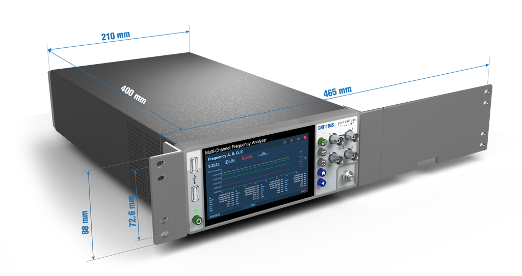
Fig. 4 Dimensions for rackmounting hardware.#
If you have ordered a 19-inch rack-mount kit for your instrument, Option 22/90 for one instrument, it has to be assembled after delivery of the instrument. The rackmount kit consists of the following:
2 brackets, (short, left; long, right)
4 screws, M5 x 8
4 screws, M6 x 8
Warning
Do not perform any internal service or adjustment of this instrument unless you are qualified to do so.
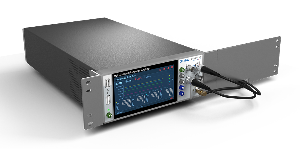
Fig. 5 Fitting the rack mount brackets on the instrument.#
Assembling the Rackmount Kit (Option 22/90)#
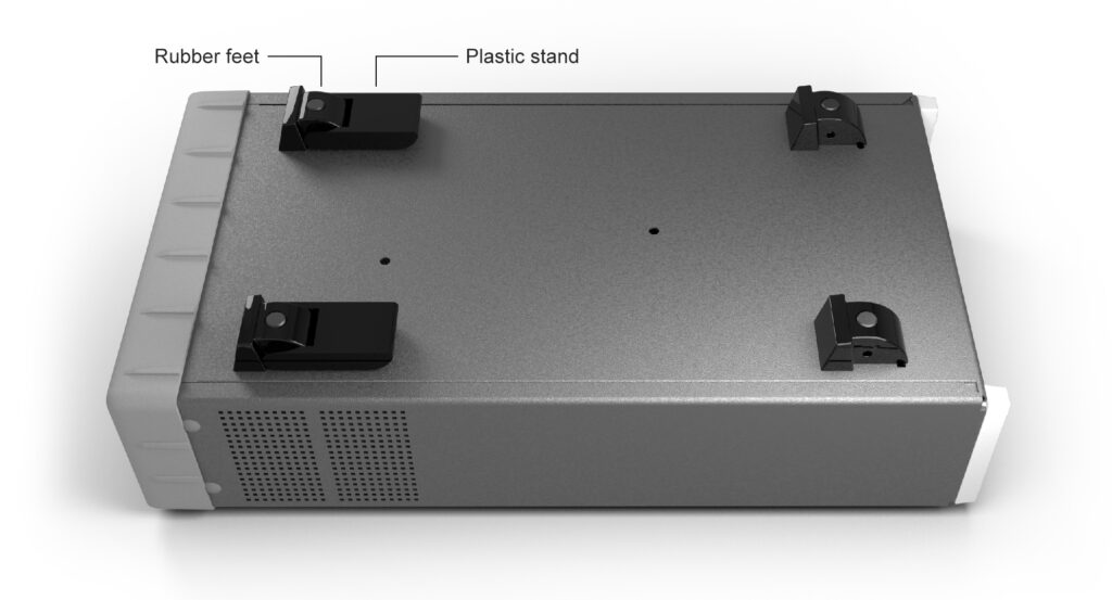
Fig. 6 Assembling the Rackmount Kit (Option 22/90)#
Turn the device upside down
Remove the rubber feet in the plastic stand
Loosen the screws underneath the rubber feet
Remove the plastic stands
Remove the four decorative plugs that cover the screw holes on the right and left side of the front panel.
The long bracket in Option 22/90 has an opening so that cables for Input signals can be routed inside the rack.
Mount the rackmount kit with the included screws
Reversing the Rackmount Kit#
The instrument may also be mounted to the right in the rack. To do so, swap the position of the two brackets.
Rackmount Adapter - two units#
This rackmount adapter can hold any two standard Pendulum ½ x 19” units.
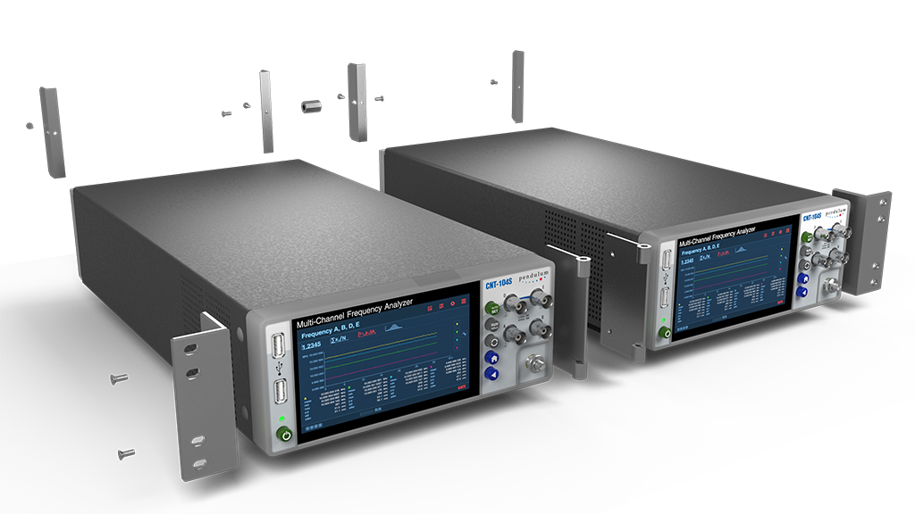
Fig. 7 Rackmount Adapter - two units#
If you have ordered the Option 22/05 rack-mount kit for two instruments, it has to be also assembled after delivery of the instrument. The rackmount kit consists of the following:
4 Brackets, rear
1 Hinge Spring Latch
2 Ear, rack
1 Assembly instruction, SXS Rack kit
2 Screws M4x8
8 Screws M5x10
1 Spacer M4x16
Assembling the Rackmount Kit (Option 22/05)#
Fig. 8 Assembling the Rackmount Kit (Option 22/05)#
Turn the devices upside down
Remove the rubber feet in the plastic stand
Loosen the screws underneath the rubber feet
Remove the plastic stands
Remove the four decorative plugs that cover the screw holes on the right and left side of the front panel.
Use the following steps to complete the side by side rack mount installation for your products. If necessary, refer to the item numbers in the following diagram for additional detail.
Determine where you would like each unit positioned (i.e., on the right or left side)
If plugs exist on the mounting holes on the front left and right side of product cover, remove and discard them
Using screwdriver, screw the rack ear (Item #2) into place using the supplied 10mm screws (Item #5)
Pinch the hinge pins together to separate the right and left hinge halves (Items #3 and 4)
Attach hinge halves to the unit with hinge facing towards the front (as displayed in diagram)
Using a screwdriver, remove the existing rear brackets on the back of each unit
Using existing machine screws removed in previous steps, attach the rear brackets supplied with the mounting kit (Item #1)
Pinch the hinge pins together into the stored position. Align the hinge halves together between the two units, and swing together side by side. The hinge pins should snap into place securing the front of the two units together
Take the supplied Hex Spacer (Item #7) and place between middle rear brackets, and secure using the supplied 8mm screws (Item #6)
Assembly is now ready for installation into standard 19” rack
Fig. 9 Rackmount Adapter - two units#
Antenna Installation#
What antenna and cabling to choose?#
It is possible to order matching antenna, mounting kit and antenna cabling directly from Pendulum Instruments. For ordering information please see Hardware Accessories.
For choosing third-party antenna and cable please consider the following:
GNSS antenna input located at the rear panel of the instrument is TNC connector. Use antenna cable with male type of TNC connector or appropriate adaptor.
The instrument supports L1 and L5 bands. Choose antenna accordingly.
The instrument outputs 5V supply voltage on antenna connector for powering active antennas. Choose active antennas with 5V power.
Use high-quality antenna cables to minimize the losses. Use low noise amplifiers if antenna cable has to be long. Make sure that the total external gain at the antenna input of the instrument is in the range of 17 to 50 dB.
Where and how to mount the antenna?#
A GNSS receiver needs to receive signals from as many satellites as possible. Optimal performance will not be available in narrow streets and underground parking lots or if objects cover the antenna. Poor visibility may result in large time phase variation and long self-survey time.
Mounting Location - Key Principles:
Unobstructed View of the Sky (360°)
In urban areas mount on a rooftop or tall mast, ideally the highest point nearby.
Avoid obstructions like buildings, trees, poles, or satellite dishes.
You need an unobstructed view of the sky above ~10° elevation angle from the horizon in all directions (e.g., 10° to 90° elevation).
Minimize Multipath Effects
Multipath happens when signals reflect off nearby surfaces and interfere with direct signals. Avoid mounting near metal surfaces, HVAC units, fences, railings and other reflective objects and surfaces. If unavoidable, use a ground plane or a choke ring antenna to reduce multipath.
Stable, Vibration-Free Surface
Mount on a rigid, stable surface to prevent movement that could affect accuracy. For high-precision timing, even tiny movements can degrade time stability.
Away From RF Interference
Keep away from high-power transmitters (cell towers, radar, TV, etc.).
Also avoid electronics that may emit EMI (electromagnetic interference).
How to Mount the GNSS Antenna:
Use a Ground Plane (if not included).
Helps reduce multipath. A 10-30 cm metal disk or plate under the antenna is often sufficient. Some antennas (like choke ring types) have this built-in.
Mount Vertically (Upward Facing)
Avoid cable sharp bends or kinks.
Weatherproofing
Use a weather-rated antenna (IP65 or better).
Use weatherproof connectors.
Install the antenna near a lightning rod, so that it lies within 45° angle from the top of the lightning rod, below it.
Bond the antenna mount to the building protection earth.
Install an inline GNSS lightning arrestor indoors at the building entry point of the cable.
Note
It must be at least 8 m of cable after the lightning arrestor to guarantee its proper function.
Getting Familiar with the Instrument#
Front Panel#

Fig. 10 Front panel#
USB Host ports. The ports allow to use keyboard/mouse to control the device, Wi-Fi dongle for wireless connection, USB Mass Storage that holds measurement results, settings presets, firmware update files.
Stand-by LED. The LED lights up when the instrument is in Stand-by mode and blinks when the display is off, but the device is powered on. In Stand-by mode internal timebase oscillator and GNSS receiver are kept powered on.
Stand-by button. Holding this button puts the instrument into Stand-by mode. For waking it up again, press the button again.
Inputs and outputs:
Output 1 — 10 MHz Out Sine Reference Outputs (BNC)
Output 2 — 10 MHz Out Sine Reference Outputs (BNC)
Output 3 — 5 MHz Out Sine Reference Output (BNC)
Output 4 — 1 PPS Out Time Reference Output (BNC)
FTR-210R also has an optional measurement input, for signals up to 400 MHz (BNC, Option 230).
Main screen. Graphics display for touch settings, result readout, graphs, status indication and more.
Stand-by button#
|
Stand-by button is located in the left side of the front panel and is intended for switching stand-by mode of the instrument. |

For putting the instrument into stand-by mode, please hold the button for 3 seconds. For waking it up again, pressing the button is enough.
In stand-by mode, the instrument is not completely disconnected from the AC mains, but remains in a state of low power consumption.
The instrument’s internal oscillator and GNSS module remain powered and continue to operate. Oscillator disciplining settings are maintained in stand-by mode.
Stand-by mode is indicated by the illuminated LED indicator above the stand-by button.
Rear Panel Inputs and Outputs#
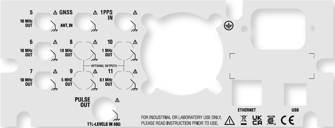
Fig. 11 Rear panel#
Rear panel has 3 standard 10 MHz Sine Reference Outputs (BNC), marked by numbers from 5 to 7.
Depending on ordered configuration, Instrument can have 4 optional outputs (BNC), marked by numbers from 8 to 11.
Please see the datasheet for detailed specifications for each output.
Option 211: 4x 10 MHz (sine).
Option 212: 0.1, 1, 5, 10 MHz (sine).
Option 213: 4x 1-pps (pulse).
Option 214: 2x 100 MHz and 2x 10 MHz outputs (sine).
There is also Optional Pulse Output (BNC, Option 132F)
Rear panel has the following inputs:
Multi-GNSS antenna input (TNC)
1PPS External Disciplining Input (BNC)
Connection of accessories and other equipment to the instrument#
The FTR-210R comes as standard with a Gbit Ethernet interface for remote control and data transfer. Use standard Ethernet 8P8C connectors and Cat 6 (recommended) or Cat 5 Ethernet cables. The instrument can be connected to Ethernet router (switch) or directly to a PC or another equipment supporting Ethernet interface.
For BNC connectors located on front and back panels use male type BNC connectors with 50 Ohm characteristic impedance. Use coaxial cables with 50 Ohm characteristic impedance coaxial cables.
On the left side of the front panel, two USB type A connectors are located. Those connectors can be used for connection of Wi-Fi adapters, mouse, keyboard, or removable flash drives. Supported list of Wi-Fi adapters see in the Specifications section. Removable flash drives must be formatted in FAT32 or exFAT file system.
USB type B connector on the rear panel is intended for service needs.
For GNSS antenna installation see Antenna Installation
Home Screen#
Note
Measurement Control and Status are only available for the instruments with purchased Measurement Option (Option 230).

Fig. 12 Home screen#
Settings#

Fig. 13 Settings screen#
Disciplining Settings#
For FTR-210R disciplining is set to “Always” by default and disciplining source is set to GNSS. This can be reconfigured via “Oscillator Disciplining” and “Disciplining Source” parameters in menu Settings → Timebase
FTR-210R can be put to Manual Holdover by setting Oscillator Disciplining to Manual Hold-Over.
Disciplining source can be selected between:
GNSS
External 1 PPS IN
1 PPS Output signal phase can be shifted in the range of -0.5 to +0.5 s with 1 ns step via “1PPS OUT Offset” parameter.
“1 PPS Output Offset” parameter is persistent configuration that is not reset by recalling defaults.
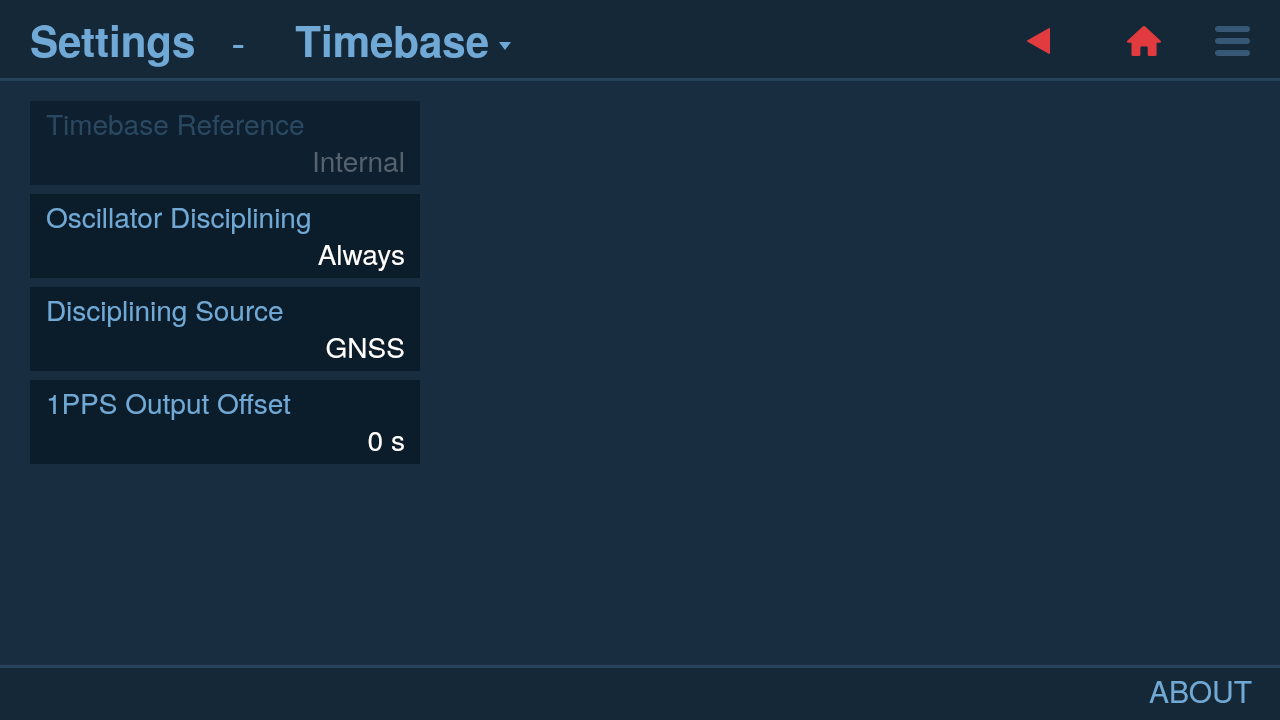
Fig. 14 Disciplining Settings#
Rubidium & Disciplining Status#
Rb Icon |
Status |
Comment |
|---|---|---|
|
Warming up |
Rubidium typically warms up in 10 min at 25°C |
|
Obtained internal lock, warmed up |
Normal operation |


Disciplining Icon |
Status |
Comment |
|---|---|---|
None |
Manual Hold-Over |
The user explicitly selected Manual Hold-Over mode |
|
Hold-over. Set to be disciplining but isn’t locked to the discipling source. |
This state is normal when the oscillator is adjusting its PPS phase to the disciplining source and usually changes to “Disciplining” in approximately 30 minutes. However, if this state lasts long time, it makes sense to check antenna, GNSS Status or external 1 PPS IN signal (if Disciplining Source is set to External 1 PPS IN) |
|
Disciplining |
Normal operation |


GNSS Settings & Status#
GNSS Settings & Status are available via Settings → GNSS
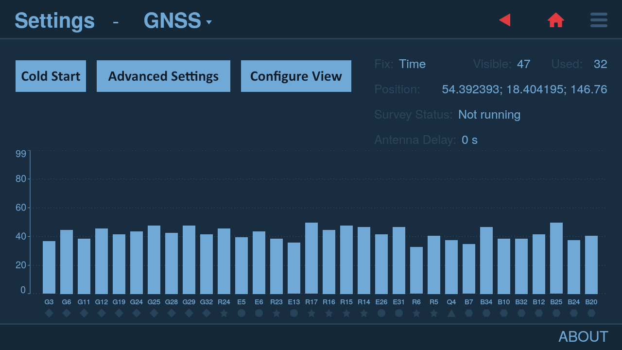
Fig. 15 GNSS Settings & Status#

Fig. 16 GNSS Advanced Settings#
Cold Start#
Cold Start will reset the GNSS receiver and all its cached data including the position and almanac.
Note
It is necessary to do Cold Start of the receiver after moving the instrument/antenna to a new location. Please also do a Cold Start when you first turn the instrument on after receiving it.
Antenna delay#
Antenna delay setting allows compensating for the signal propagation through the antenna and the cable. Please refer to the specification of particular antenna and cable for the typical propagation delay figures or measure the actual propagation delay of your setup for maximum accuracy.
Please see below a table with typical figures for the optional HW accessories available directly from Pendulum Instruments:
Accessory |
Delay, ns |
Comment |
|---|---|---|
Option 01/200
Multi-GNSS Antenna
|
<10 |
Based on group delay variation across the GNSS band |
Option 02/20T
Antenna Cable, 20 m
|
78.5 |
Cable’s Velocity of Propagation factor is 85%
(corresponds to 3.92 ns/m)
|
Option 02/25T
Antenna Cable, 25 m
|
98 |
|
Option 02/50T
Antenna Cable, 50 m
|
196 |
|
Option 02/130T
Antenna Cable, 130 m
|
510 |
Self-survey#
Self-survey is a special feature of timing GNSS receivers which allows to first average the position down to required accuracy, then fix it and continue solving GNSS navigation equations for time only, thus maximizing the timing accuracy.
It is controlled by 2 parameters: Survey-in Accuracy and Time. The former specifies the required averaged position accuracy while the latter one will make sure the survey won’t finish before specified period even if the required accuracy has been reached.
Note
Self-survey is never run automatically after it has completed at least once. On power up the instrument will use fixed position which is the result of the last successful self-survey. To force self-survey (e.g. after moving the instrument/antenna to a new location) please use Cold Start button under Settings → GNSS. Changing self-survey parameters (Settings → GNSS → Advanced) will also force self-survey to be restarted.
Note
Depending on the antenna location, possible interferences and other factors which have impact on the GNSS signal reception, it might be not possible to reach desired position accuracy. In this case it is necessary to relax the survey accuracy and survey time parameters.
Used Signals#
This parameter allows to select particular GNSS signals to be used. Normally it shouldn’t be modified unless there are known issues with particular signal or some restrictions apply.
Status#
The GNSS Status screen displays the following information about the current GNSS receiver state:
Fix. Can be of the following values:
No fix. This means the GNSS receiver cannot determine positional and timing information yet. Under normal conditions and good sky view GNSS receiver will typically obtain the first fix in less than 5 min. If this status continues longer than 5 minutes this may indicate poor GNSS reception.
3D fix (minimum 4 satellites available). The receiver is successfully solving for position and time, but self-survey has not completed yet.
2D fix (minimum 3 satellites available). Last known altitude is kept constant and the receiver is solving for latitude/longitude and time only.
Time. Self-survey has been completed. The receiver fixes the position averaged during the self-survey and keeps solving for time only. Time solution can be calculated with 1-2 satellites. Time fix allows for maximum timing accuracy.
Visible. Number of satellites in view
Used. Number of satellites used for the solution.
Position (latitude; longitude; altitude)
Survey Status. Shows overall the self survey progress relative to minimum survey time (set by Survey-in Time setting).
Note
If minimum survey time has passed but required position accuracy (set by Survey-in Accuracy setting) has not been reached yet, the progress will be indicating 99%.
Antenna delay currently set
Satellites chart shows the following information about satellites currently in view:
Satellite ID - under the bar.
Constellation symbol under the ID. For the legend - see Configure View drop-down selection
Signal to noise ratio (SNR) - bar height.
If particular satellites is used for solution (filled SNR bar) or not (empty SNR bar)
Configure View drop-down menu can be used to remove information regarding certain constellations from the satellite chart.
Note
Configure View selection has impact only on the Satellite Chart, it doesn’t exclude the unselected constellations from the solution. To exclude certain constellations or signals from GNSS solution please use Settings → GNSS → Advanced → Used Signals.
Measurement Settings#
Note
Measurement Settings are only available for the instruments with purchased Measurement Option.
Please refer to CNT-100 series Frequency Analyzer User Manual for detailed information regarding measurement settings.
See Measurements for info how to set up particular measurements in FTR-210R GNSS disciplined Frequency and Time Reference.
Traceability (Option)#
FTR-210R GNSS disciplined Frequency & Time Reference traceability data is continuously saved to internal database.
The user can export calibration report and accompanying raw data for configurable time period via Settings → Calibration report
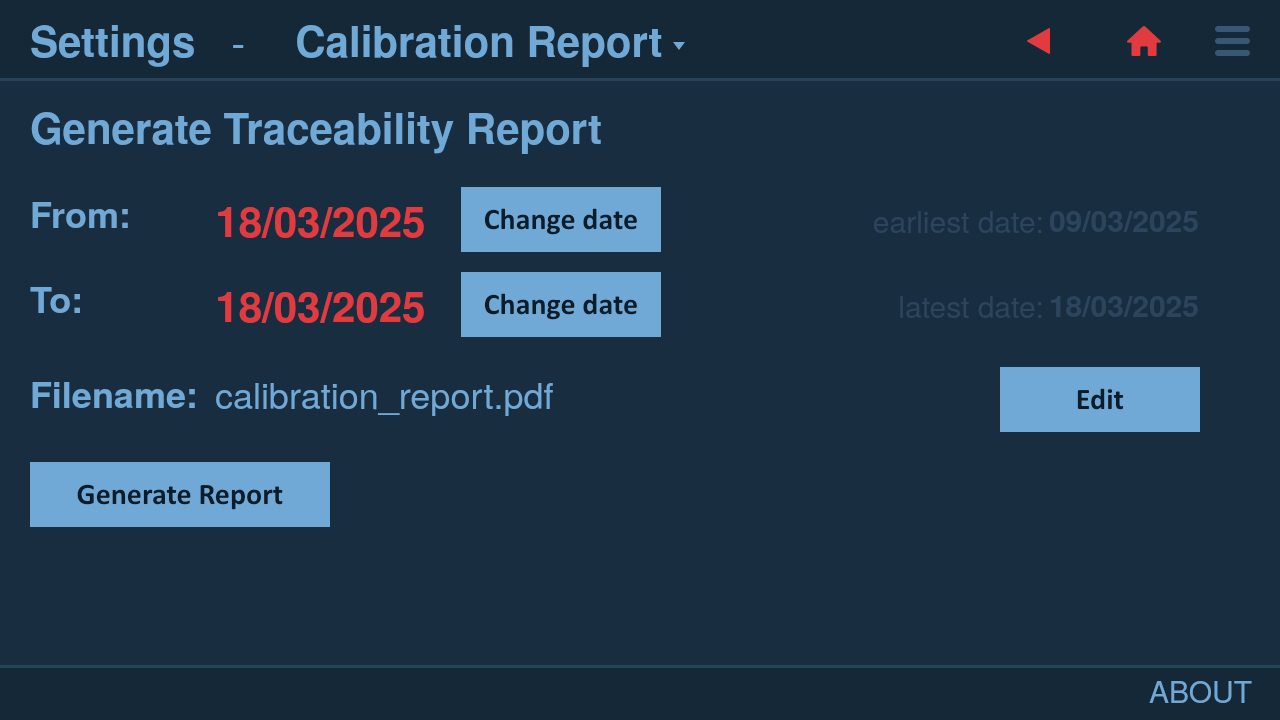
Fig. 17 Calibration Report export user interface#
Upon pressing Generate Report button 2 files are saved to the instrument’s internal memory:
Calibration Report in PDF format with traceable calibration figures, uncertainties and calibration procedure description,
Raw data in CSV format.
Raw data CSV file contains records of:
UTC time,
Whole part of internal timestamp (in 700 MHz clock ticks),
Flags (hexadecimal value)
Bit 0: Hold-Over
Bit 1: Manual Hold-Over
Bit 2: UTC time not valid
Bit 3: No GNSS fix
Bit 4: No GNSS Time fix (self-survey has not been completed)
Bit 5: The instrument has been restarted
Fractional part of internal timestamp (in 1/65536 parts of 700 MHz clock ticks)
Estimated 1 PPS phase error
Current DAC code used for internal timebase frequency adjustment
The report files can be downloaded at any time in one of 2 ways:
Downloading via File Download section of the instrument web interface
Copying to USB stick via Settings → User Options → File Manager
CSV file can be opened in e.g. Excel to further post-process and/or visualize the data.
Note
Phase offset values obtained during periods when 1 PPS and UTC time from GNSS are not reliable (no fix) are not saved and not taken into account for the mean offsets calculations.
Measurement Data Display#
Note
Measurement Data Display is only available for the instruments with purchased Measurement Option.
View large numeric data along with auxiliary data (e.g. voltage):
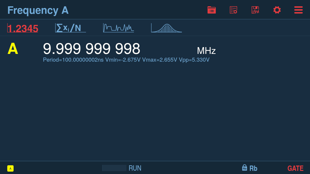
Fig. 18 Numeric screen#
View detailed statistics for all measurement channels (click numbers for particular channel to zoom):
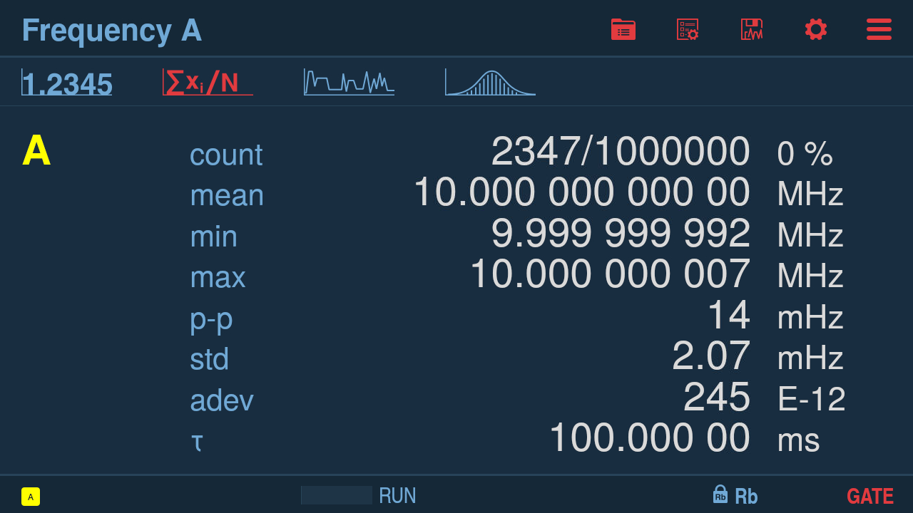
Fig. 19 Statistics screen#
View graph and distribution along with detailed statistics (click numbers for particular channel to zoom):
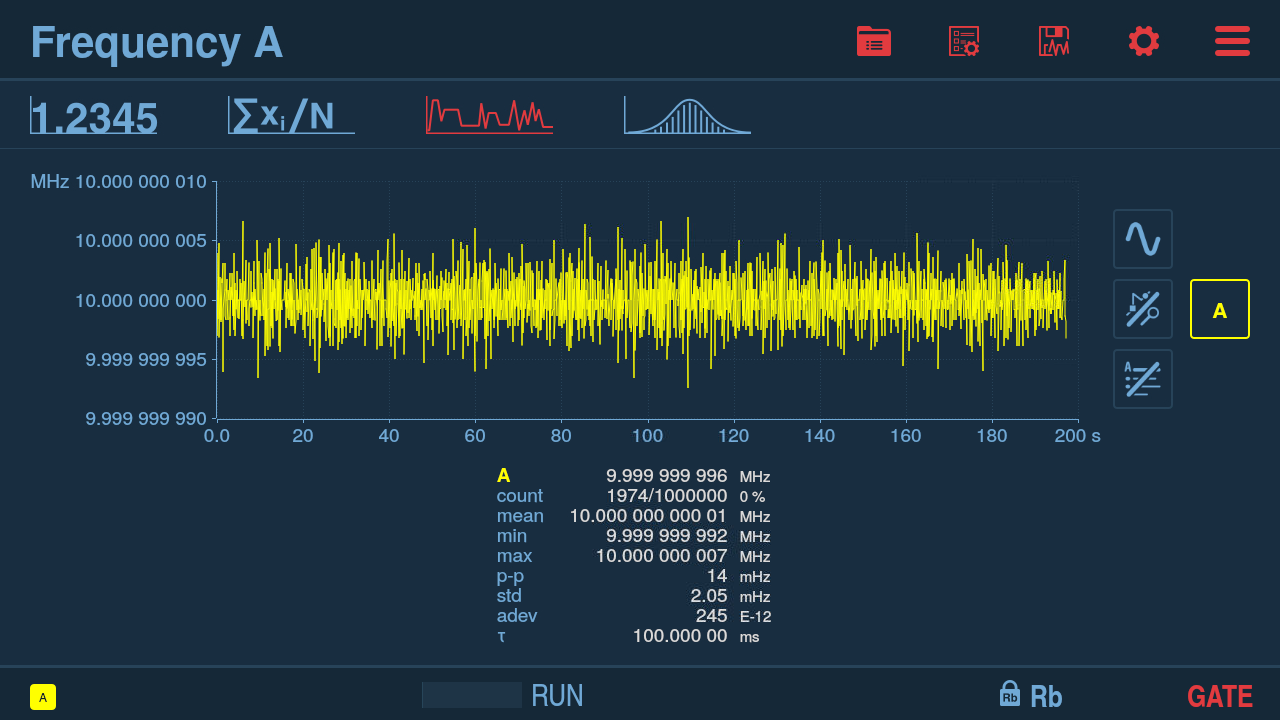
Fig. 20 Graphs screen#
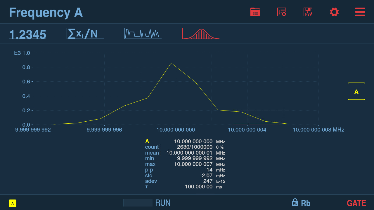
Fig. 21 Distribution graph screen#
Measurements#
Note
Requires Option 230 (Measurement input)
Frequency/Period Average measurements#
In this measurement mode each sample is a Frequency/Period value averaged over sample interval (which acts as gate).
This is back-to-back measurement with no dead-time between the samples.
Minimal sample interval is 50 ns or 1 µs (depending on particular model and corresponding license installed). Up to 32 million samples total can be measured in a single measurement session. Resolution is 12 digits per 1 s of gate time (Sample Interval).
If the signal period is greater or equal to the set Sample Interval – each signal period can be captured. When measuring Frequency/Period Average on input A and Trigger Mode is set to Auto or Relative, wide hysteresis (see details below) is used to improve noise tolerance. In this mode 2 comparators with different trigger levels are used for each input. First trigger level (e.g. Trigger Level A) defines the upper limit of wide hysteresis band and the second one (e.g. Trigger Level A2) defines the lower limit. Trigger Mode Auto sets trigger levels to 60% and 40% of signal’s voltage range and Relative allows modifying them to fine tune the hysteresis band.
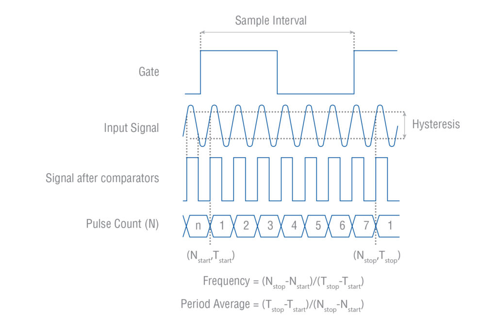
Fig. 22 Frequency/Period Average measurement with Wide Hysteresis#
Without wide hysteresis, the signal needs to cross the approx. 20 mV in case of 1x Attenuation (200 mV in case of 10x) input hysteresis band before triggering occurs. This hysteresis prevents the input from self-oscillating and reduces its sensitivity to noise. If signal noise is comparable or higher than hysteresis band – it can result in false extra triggering producing erroneous counts. These could ruin the measurement.
Fig. 23 shows how spurious signals can cause the input signal to cross the trigger or hysteresis window more than once per input cycle and give erroneous counts. Fig. 24 shows that a wide enough hysteresis prevents false counts.
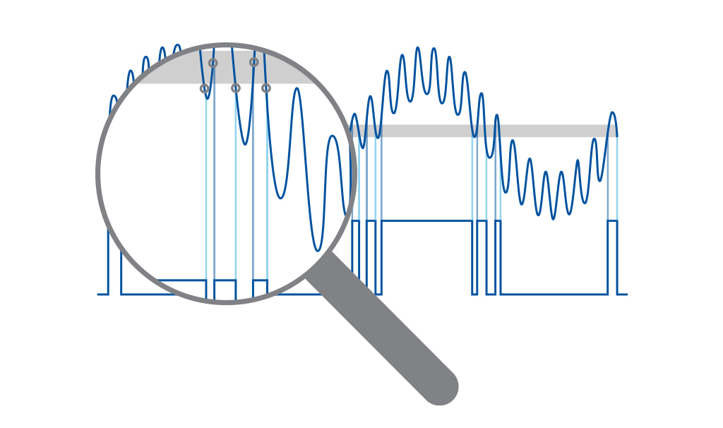
Fig. 23 Too narrow hysteresis gives erroneous triggering on noisy signals.#
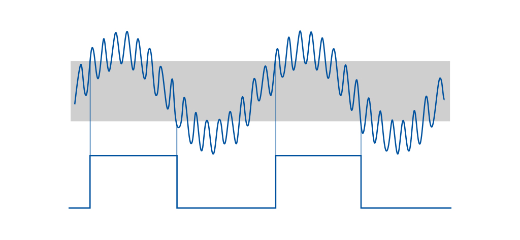
Fig. 24 Wide trigger hysteresis gives correct triggering.#
Frequency Offset measurements (Calibrator Use-case)#
Note
License is needed to unlock Frequency Offset option (Option 152F).
The optional measurement input converts FTR-210R to a 1-box Frequency Calibrator. Using the Frequency Offset function, the Frequency of the device under test can be displayed as relative deviation with automatic tolerance limits control.
When using Frequency Offset function the user can use Settings → Measurement → Frequency Tolerance to specify the required DUT tolerance limits and Sample Interval will be set automatically based on the tolerance value.
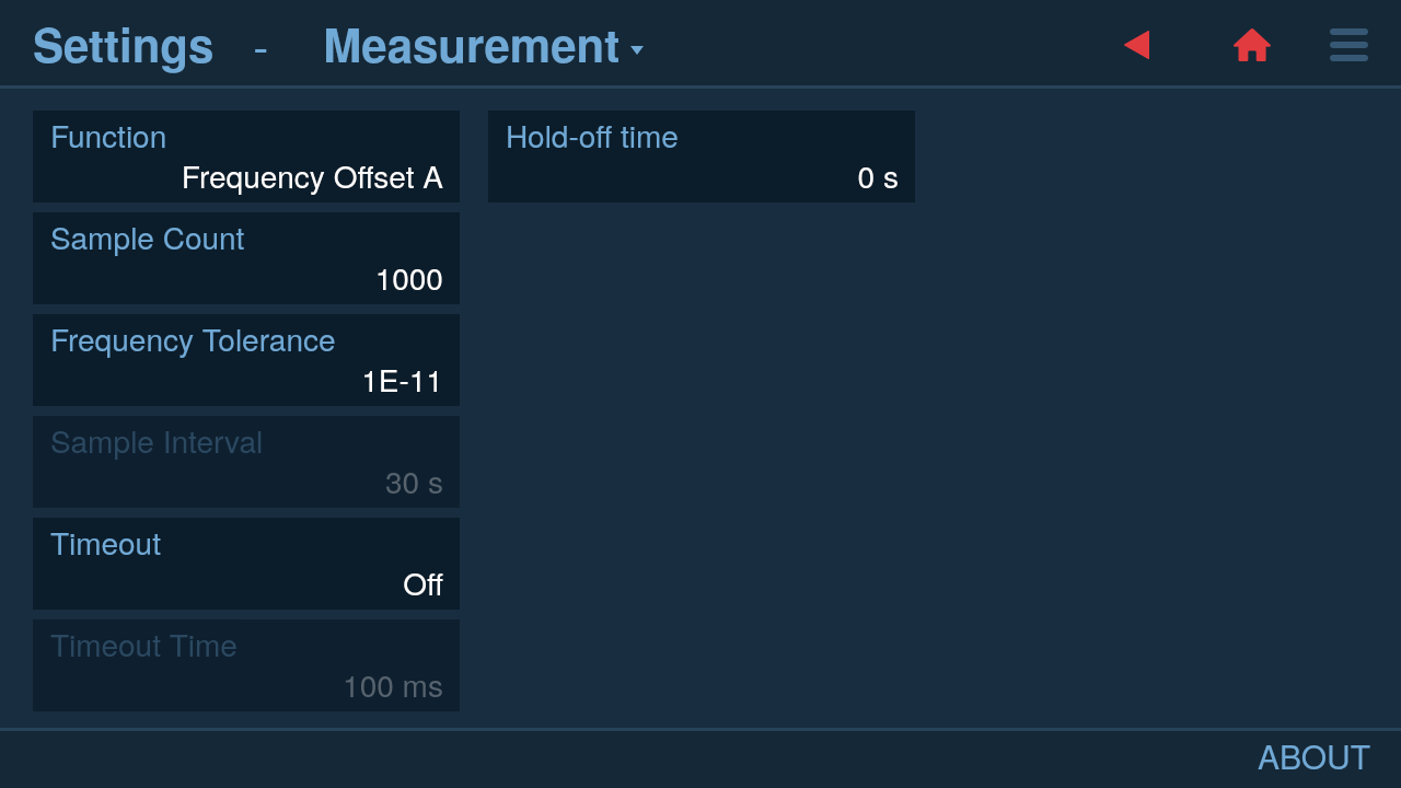
Fig. 25 Setting calibration tolerance for Frequency Offset function (Frequency Tolerance setting)#
The Limits function is automatically activated with limits set to calibration tolerance. In combination with clear pass/fail indicators this further eases the manual or semi-automatic calibration.
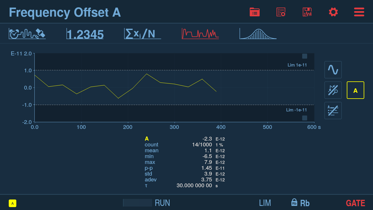
Fig. 26 Example of calibration measurement trend graph#
Time Interval Error (TIE)#
Note
License is needed to unlock TIE option (Option 151F).
TIE measurement uses continuous back-to-back time-stamping to observe slow phase shifts (wander) in nominally stable signals during extended periods of time. The measurement itself is performed the same way as Frequency/Period Average but different processing is applied.
TIE is only applicable to clock signals, not data signals. Monitoring distributed PLL clocks in synchronous data transmission systems is a typical application.
The nominal frequency of the signal under test can be either manually or automatically set. Auto detects the frequency from the first samples, and rounds to number of digits set by the user (5 by default). TIE is measured as the period deviation of the input signal from the “ideal” reference period, and the accumulated deviation, up or down, is calculated for each Sample Interval, and displayed.
Minimal sample interval is 50 ns or 1 µs (depending on particular model and corresponding license installed). Up to 32 million samples total can be measured in a single measurement session.
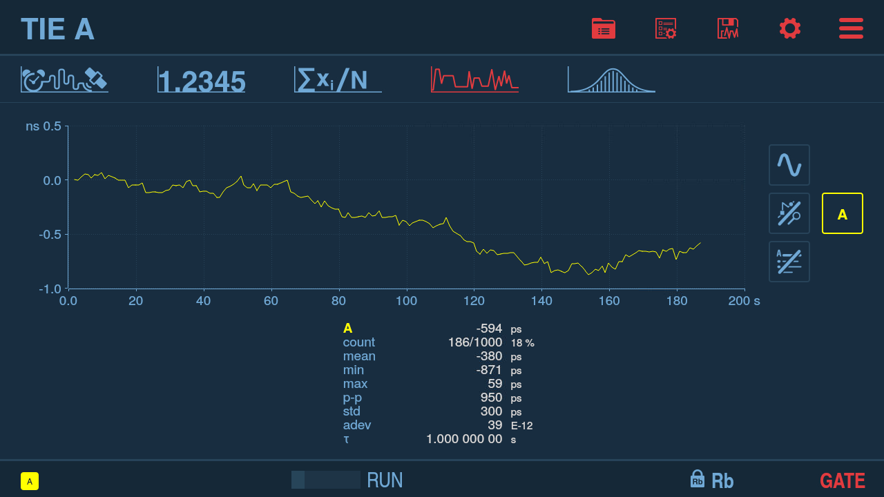
Fig. 27 Example of TIE measurement trend graph#
Pulse characterization#
Positive and Negative Pulse Width#
Positive pulse width measures the time between a rising edge and the next falling edge of the signal. Negative pulse width measures the time between a falling edge and the next rising edge of the signal.
The selected trigger slope is the start trigger slope. The instrument automatically selects the inverse polarity as stop slope.
This is not a back-to-back measurement, meaning that there is a dead-time of 50 ns or 1 µs (depending on particular model and corresponding license installed) between the samples. Up to 16 million samples total can be measured in a single measurement session.
Rise Time, Fall Time#
By convention, rise/fall time measurements are made with the trigger levels set to 10% (start) and 90% (stop) of the maximum pulse amplitude. For ECL circuits, the reference levels are instead nominally 20 % (start) and 80 % (stop). In this case one can use Relative Trigger Levels mode and set trigger levels to 20% and 80% respectively.
These are not a back-to-back measurement, meaning that there is a dead-time of 50 ns or 1 µs (depending on particular model and corresponding license installed) between the samples. Up to 16 million samples total can be measured in a single measurement session.
Positive and Negative Slew Rate#
Slew rate is the speed of voltage change on pulse positive or negative edge. Hence, Positive and Negative Slew Rate are based on Rise Time and Fall Time measurements, the following formulae are applied (1):
Hold-off#
Hold- off function allows to insert dead-time into input trigger circuit which effectively acts as a digital lowpass filter. Hold-off can be set to 0 (Hold-off OFF) or in the range [20 ns .. 2.683 s] which correspond to low-pass filter frequency from 100 MHz down to 0.5 Hz.
Setting Hold-off to approx. 75% of the cycle time of the signal allows to inhibit erroneous triggering for noisy signals.

Fig. 28 Using hold-off as a Digital LP filter to cope with erroneous triggering on noisy signal#
Hold-off is also an effective measure to cope with contact bouncing on the front of the signal under test.

Fig. 29 Using Hold-off to cope with switch bounce effect#
You should be aware of a few limitations to be able to use the Hold-off feature effectively and nambiguously. First you must have a rough idea of the frequency to be measured. A cutoff frequency that is too low might give a perfectly stable reading that is too low. In such a case, triggering occurs only on every 2nd, 3rd or 4th cycle. A cutoff frequency that is too high (>2 times the input frequency) also leads to a stable reading. Here one noise pulse is counted for each half-cycle.
Timeout#
The instrument ends measurement when all requested samples have been collected. However, if signal is absent (or lost) on one of the inputs used for the measurement – timestamps from this channel will never come and instrument will wait forever unless measurement is stopped explicitly.
However, in many cases this is undesirable behavior. For example in an automated test system when absence of signal can be a result of a wrong test setup or device under test malfunction, it is would be a waste of time to wait until the expected end of a long measurement to discover that one of the signals is just missing.
This is where Timeout function comes to help. If Timeout is ON, the measurement will end in case there are no samples from one of measurement inputs for the time duration set by Timeout Time.
Calibration#
Internal Calibration#
The instrument has a possibility to compensate for some internal sources of error by the means of internal calibration. This procedure doesn’t require any external signal, the instrument can perform it automatically.
Performing internal calibration before the start of measurement helps getting maximum accuracy and best resolution. However, because internal calibration takes up to 2 s it has impact on measurement speed which might be important in automated test systems. Hence, the instrument allows to choose the schedule of internal calibration. Summarizes available options.
Mode |
Description |
Every 30 minutes |
The instrument performs internal calibration every 30 minutes between successive measurements or when it is idle. This is the default option which provides the best trade-off between accuracy, resolution and average measurement speed. |
Before every measurement |
The instrument performs internal calibration before each timing measurement to ensure best resolution and accuracy. This results in additional time overhead of around 2 s per measurement session. If such overhead is not critical – this is the recommended choice. |
Once (after warm-up) |
The instrument performs internal calibration only once – after the instrument has warmed up. This guarantees no calibration overhead, but resolution will deteriorate over time. |
Table 4. Internal Calibration Modes
To provide maximum flexibility, the instrument also provides the possibility to perform internal calibration explicitly. This is especially useful when Interpolator Calibration Mode is set to Once.
All above can be configured under Settings → Advanced section (see Fig. 30).

Fig. 30 Internal Calibration configuration#
Timebase Calibration#
Note
For FTR-210R timebase calibration is not required unless the instrument is used in Hold-over or Manual Hold-over modes
For increasing measurement accuracy, a good reference source can be used for timebase calibration. Connect the source to Input A, select Settings→Timebase Calibration, choose reference frequency and start the procedure. It is possible to interrupt the process midway, re-apply result from previous calibration or reset to factory calibration setting.

Fig. 31 Timebase Calibration menu#
Voltage Calibration#
For increasing accuracy of voltage measurements and manual trigger level setting accuracy, a good source of DC voltage can be used for voltage calibration. Open Settings → Voltage menu, select the input to be calibrated and follow the instructions.
Note
Pictures below illustrate display of CNT-104S model.
For CNT-102, channels D, E are not available and areas, fields and graphical objects for corresponding to these channel are not present. Up to 2 signals can be measured in parallel.
For FTR-210R, channels B, D, E, C are not available and areas, fields and graphical objects for corresponding to these channel are not present. Only one signal can be measured in parallel.

Fig. 32 Voltage Calibration menu#
Note
Voltage calibration sets inputs to 1 MOhm impedance.
Mathematics#
The instrument can use five mathematical expressions to process the measurement result before it is displayed:
K×X+L
K/X+L
(K×X+L)/M
(K/X+L)/M
X/M-1
Select Settings → Math / Limits to enter the Math / Limits submenu.

Fig. 33 Mathematics menu#
The default values of K (Scale factor), L (Offset) and M (Reference value) are chosen to 1, 0 and 1 respectively, so that the measurement result is not affected directly after activating Math. Recalling the default setting will restore these values as well.
It is possible to apply Mathematics function to all measurement series or to selected one.
When Mathematics is turned on, the instrument status bart shows MATH indicator.
Example use cases#
If you want to observe the deviation from a nominal frequency, for example 10 MHz, instead of the absolute frequency itself, you can do like this:
Select Math
Select the expression K×X+L
Select K = 1 (if not already set)
Select L = -10 MHz
Now the display will show the deviation from the value you have just entered.
By changing the constant K you can scale the result instead. Set for example K = 60 to convert Frequency in Hz to RPM (revolutions per minute) from rotation transducers.
Use the expression X/M-1 if you want the result to be displayed as a relative deviation. The result will be displayed as
%, ‰ (per mille or one-thousandth), ppm, ppb, or as a dimensionless number like +1.2345E-12.
Limits#
Limits feature is used for setting numerical limits and selecting the way the instrument will report the measurement results in relation to them.

Fig. 34 Limits configuration#
Limit Behavior setting defines how the device will react on limits:
Off – limits are not checked.
Capture – only samples meeting the limit criterion are captured, the rest are discarded. Limit status is displayed.
Alarm – all samples are captured; limit status is displayed.
Alarm Stop – measurement session stops if measured value doesn’t meet the limit criterion.
Limit Type:
Above – results above set Lower Limit will pass.
Below – results below set Upper Limit will pass.
Range – results within the set limits will pass.
Limits can be applied to all measurement series or to selected one, depending on user’s choice.
When Limit Behavior is not Off, the instrument status bar shows LIM. It will change to LIM! if at least one sample didn’t meet set Limit criterion during measurement session.
Numeric, Graph and Distribution screens will also have additional Limit indicators displayed.
Note
Pictures below illustrate display of CNT-104S model.
For CNT-102, channels D, E are not available and areas, fields and graphical objects for corresponding to these channel are not present. Up to 2 signals can be measured in parallel.
For FTR-210R, channels B, D, E, C are not available and areas, fields and graphical objects for corresponding to these channel are not present. Only one signal can be measured in parallel.

Fig. 35 Limits display#
Pulse Output (option)#
Note
License is needed to unlock Pulse Output functionality in the instrument.

Fig. 36 Pulse Output configuration#
Pulse Output is located on rear panel of the instrument and can be used for one of the following purposes:
Pulse Generator. Pulse period can be selected in [10 ns .. 2.147 s] range in 2 ns steps, pulse width – from 6 ns in 2 ns steps. Pulse width must be at least 4 ns lower than period.
Gate Open. High level indicates that measurement is in progress.
Alarm Out. Indicates when Limits Alarm is active. Can be selected between Active High and Active Low
Irrespective to the selected mode, the amplitude of Pulse Output signal is set to TTL levels into 50 Ohm termination
ADEV Graph (option)#
Note
A license (option 161F) is required to unlock ADEV graph in the instrument.
Allan deviation (ADEV) is a commonly used way to analyze noise and estimate signal stability.
ADEV Graph option enables calculation of ADEV values for a range of intervals, displays results in graphical and textual form, with possibility to save them into a file. The instrument uses ‘overlapped ADEV’ as a method of calculation. For detailed specifications, including ADEV floor, please check instrument’s datasheet.

Fig. 37 ADEV graph tab#

Fig. 38 ADEV graph setting#
ADEV Graph is turned Off by default (to avoid performance penalties on fast measurements) and can be enabled via the settings menu: “Settings->Measurement->ADEV Graph->On” (see Fig. 38)
The data are displayed on the graph in logarithmic horiozontal and vertical axes. The vertical axis represents ADEV values and horizontal values - observation intervals (τ). The graph is constantly updated during measurement.
ADEV values for most typical observation intervals (only powers of ten), are displayed under the graph. Touching that area (clicking with mouse pointer) will open a window with more detailed table of ADEV values (Fig. 39)

Fig. 39 ADEV(tau) detailed list#
There is a possibility to save results to a file using “Save measurement” button. The file will be created in user partition and named as “<Date>_<Function>_ADEV.csv”, where <Date> is current date and <Function> is measurement function.
Allan Deviation can be calculated from Frequency data (measurement functions Frequency, Period Average) or phase data (measurement functions TIE, Time Interval, Time Interval Single, Dual Time Interval). Allan Deviation calculation only makes sense for zero dead time back-to-back measurements.
Tip
Please note that calculating Allan Deviation from measurement data which use linear regression techniques (i.e. Smart Frequency and Smart Period Average) is not possible. Attempts of applying ADEV formulas to the data obtained from “smart measurement” will NOT yield correct Allan Deviation.
Time Interval measurements and Allan Deviation#
In case of measurement functions “Time Interval X,Y,Z,U” or Time Interval Single “X,Y,Z,U” (where X, Y, Z, U represent selected measurement inputs, for example A, B, D, E) the reference/etalon signal is to be connected to the input X, and DUTs (devices to tests, for example oscillators), are to be connected to Y,Z,U. Signals on all inputs must have same nominal frequency. Depending on exact model of the instrument, some of the inputs referred as X, Y, Z, U may be not available.
In case of Dual Time Interval X,Y,Z,U the reference/etalon signals are to be connected to inputs X and Z and DUTs - to Y and U. The signals on inputs X and Y must have same nominal frequency, and also signals on Z and U must have same nominal frequency. Dual Time Interval function is available only on instruments with 4 measurement channels.
This way, resulting Time Interval series are essentially absolute differential TIE (or phase error) of DUTs relative to the reference/etalon signal(s).
Down-converted signals and Allan Deviation#
For the case when input signals are result of signal down-conversion (e.g. to bring high frequency signal to the acceptable range or to improve the Allan Deviation floor) it is convenient to use Math function (Settings -> Math/Limits) to account for down-conversion and get ADEV results for the original signal.
The Math function should be configured the following way (under Settings -> Math/Limits):
Math Mode = K * X + L
Coefficient L = 0
Coefficient K depends on which measurement function is used:
K = F_nom_orig / F_nom_downconverted for Frequency measurement function
K = F_nom_downconverted / F_nom_orig for Time Interval, Time Interval Single, Dual Time Interval, Period Average,
where F_nom_orig - nominal frequency of the signal before the down-conversion, F_nom_downconverted - nominal frequency of the signal after the down-conversion.
For TIE measurement function, using Math in this case is not needed. Just set Settings -> TIE Reference Frequency to F_nom_downconverted.
For Math Modes other than K * X + L, Allan Deviation calculation is not performed.
Network#
The instrument supports wired 10/100/1000 Mbps connection as well as wireless (via external USB Wi-Fi adapter).
It has IPv4 support and can be configured in either Static or Dynamic (DHCP) mode. If Static mode is selected, user is expected to manually enter IP address, Network mask and Gateway. For Dynamic mode, these fields are read-only and display IP address, network mask and gateway that are currently in use.

Fig. 40 Network configuration#
Web Interface#
The instrument has built in web server that provides Web Interface allowing to see the instrument screen and control it remotely, download files and upgrade firmware.
Note
Pictures below illustrate display of CNT-104S model.
For CNT-102, channels D, E are not available and areas, fields and graphical objects for corresponding to these channel are not present. Up to 2 signals can be measured in parallel.
For FTR-210R, channels B, D, E, C are not available and areas, fields and graphical objects for corresponding to these channel are not present. Only one signal can be measured in parallel.

Fig. 41 Web Interface#

Fig. 42 Firmware Update page of the Web Interface#

Fig. 43 File Download page of the Web Interface#
VNC#
The instrument also exposes VNC server on port 5901 which allows remote access and control. One can use any VNC client software on PC, mobile phone or tablet.
Front USB ports#
Front panel USB ports can be used for connecting:
Peripherals (PC keyboard and mouse) which complement the touch screen interface.
USB storage for saving measurement results, presets or upgrading firmware.
Wi-Fi adapter for enabling wireless networking. Please check the datasheet for the list of supported dongles that were tested for compatibility. Other models may be missing a driver and not work out-of-the-box.
Note
Only FAT32 and exFAT filesystems are supported for USB sticks. NTFS is not supported.
File Manager#
The instrument has built-in File Manager accessible via Settings → User Options → File Manager or dedicated icon on measurement screen.

Firmware Update#
There are 2 ways of updating firmware of the instrument:
Update via Web Interface (preferred):
Download SW update file (it has .swu extension) to your PC
Connect the instrument to LAN: either via Ethernet cable or use supported Wi-Fi dongle to connect via Wi-Fi
On the instrument open Settings → User Options → Network to check or set current IP address
On PC open web browser and type the instrument address to address field. The instrument’s Web Interface will open
Click Software Update link on top right and follow the instructions
Update via USB stick:
Note
Only FAT32 and exFAT filesystems are supported for USB sticks. NTFS is not supported.
Copy SW update file to the USB stick. The file has .swu extension
Insert the USB stick to one of the instrument’s front panel USB ports
Navigate to Settings → User Options → Firmware Update
On Firmware Update screen tap/click on SW update file. SW update will start. No progress indication will be displayed – wait until the instrument reboots
Installing license#
Note
Only FAT32 and exFAT filesystems are supported for USB sticks. NTFS is not supported.
Put License File on USB stick
Insert the USB stick to one of the instrument’s front panel USB ports
Navigate to Settings → User Options → Import License
Select License to be imported. After confirmation the user interface will-reload to activate the new license.
Performance Check#
General Information#
Before turning on the instrument, ensure that it has been installed in accordance with the Installation Instructions outlined in the Chapter Installation of this Manual.
This performance procedure is intended for incoming inspection to determine the acceptability of newly purchased instruments.
Note
The procedure does not check every facet of the instrument. It is concerned primarily with those parts of the instrument which are essential for determining the function of the instrument.
Note
This GNSS-controlled Frequency Reference is continuously calibrated via the GNSS-signal as long as there is a sufficient contact with the GNSS-satellites. It is not necessary to remove the cover of the instrument to perform frequency calibration. If Traceability option (Option 220) is installed the instrument does not need to be sent away for frequency calibration.
Recommended Test Equipment
DSO with 50 Ohm input
CNT-100 series Multi-Channel Frequency Analyzer
Preparations#
Power up your instrument at least 30 minutes before checking to let it reach normal operating temperature. Failure to do so may result in certain test steps not meeting equipment specifications.
Connect the antenna including cable to the antenna input (rear)
Power-On Test#
Connect the power cord. At power-on the frequency standard performs an automatic Internal Self-Tests
Internal self-tests are run on every instrument power up. In case of a failure information message box appears described the type of the error.
Note
Power up your instrument at least 30 minutes before continuing. This will allow the instrument to reach normal operating temperature and go into GNSS-locked mode.
Touch Panel Test#
Press Settings icon on top right. Open User Options → Recall Defaults. Confirmation dialog will appear.
Press Yes.
Press BACK icon on top right. Main Settings screen will appear.
Press ABOUT in bottom right corner. About box will appear.
Press OK.
Press HOME icon on top right. Main screen will appear.
Frequency Offset Calculation Test (only for Option 220)#
After 24h the calculated frequency offset value may be far from the specification. After 48h the frequency offset value should be near the specification \(1 * 10^{-12}\). If not, check if it has had continuous satellite contact and that the ambient temperature has been stable (within ± 3 degrees). Redo the test.
Front and Rear Panel Outputs#
10 MHz#
Connect a DSO with 50 Ohm inputs to all “10 MHz Out” BNC-connectors, one at a time. Verify that the output signal is sinusoidal and that the voltage is at least 900 mVrms. Connect a CNT-100 series Multi-Channel Frequency Analyzer and verify that the frequency is 10 MHz ± 0.01 Hz.
5 MHz#
Connect a DSO with 50 Ohm inputs to the “5 MHz Out” BNC-connector. Verify that the output signal is sinusoidal and that the voltage is at least 900 mVrms. Connect a CNT-100 series Multi-Channel Frequency Analyzer and verify that the frequency is 5 MHz ± 0.005 Hz.
1 PPS#
Connect a DSO with 50 Ohm inputs to the “1 pps Out” BNC-connector. Verify that the voltage is a square wave and that the low level is <0.9V and the high level >1.8V. Connect a CNT-100 series Multi-Channel Frequency Analyzer and verify that the frequency is 1Hz ± 1 µHz.
Optional Ref. Frequency outputs (4x BNC)#
Option 211: 4x 10 MHz (sine)
Option 212: 0.1, 1, 5, 10 MHz (sine)
Connect a DSO with 50 Ohm inputs to all BNC-connectors, one at a time. Verify that the four sine wave output signals are sinusoidal and that the voltage is at least 1Vrms.
Connect a CNT-100 series Multi-Channel Frequency Analyzer and verify that the frequency is 10 MHz ± 0.01 Hz, 5 MHz ± 0.005 Hz, 1 MHz ± Hz and 0.1 MHz ± 0.0001 Hz respectively.
Option 213: 4x 1-pps (pulse)
Option 214: 2x 100 MHz and 2x 10 MHz outputs (sine)
Pulse Output (Option 132F)#
Connect a DSO with 50 Ohm inputs to the “Pulse Out” BNC-connector. Verify that the voltage is a square wave and that the low level is <0.9 V and the high level >1.8 V. Connect a CNT-100 series Multi-Channel Frequency Analyzer and verify that the frequency is 1 Hz ± 1 µHz (factory default setting is 1 Hz).
Measuring Input Functions (Option 230)#
For performance check of measuring functions, please refer to Chapter 8. Performance Check of CNT-100 series Multi-Channel Frequency Analyzer User Manual.
Preventive Maintenance#
Calibration#
Calibration and adjustment in the traditional sense are not necessary as long as the instrument is operating in disciplined mode. Then the internal rubidium timebase is continuously monitored and forced to follow the cesium clocks of the navigational satellites. These clocks are traceable to, for instance, NIST and USNO. Thus the normal aging characteristics of the internal timebase will be concealed. However, if the device is operating in hold-over mode for long periods, the aging characteristics are no longer concealed. Then you may need to reset the timebase from time to time by letting the device operate in disciplined mode for at least 48 hours.
Calibration intervals#
Normally it is quite adequate to check the frequency deviation between one of the reference outputs and a corresponding, independent, cesium-controlled reference source once a year. Shorter intervals may be necessary if the main operating mode is hold-over, and the allowed deviation is less than the specified annual aging. See the timebase specifications to collect the data for these calculations.
Traceability option (Option 220)#
With the traceability option there is NO NEED to ever send the instrument away for a traceable calibration. The instrument is continuously calibrating the internal Rubidium to UTC and can print traceable calibration reports at any desired time.
Maintenance of internal components#
There are no parts or components inside the instrument that are serviceable by user. Power supply inside the instrument is not serviceable.
Handling of the removable battery#
This instrument uses a 3 V cell lithium battery of type CR1220 to power real time clock. The instrument controls the state of the battery and notifies if the battery needs replacement with a message box on its screen, at start up. The battery is installed in a dedicated holder inside the instrument and can be replaced by qualified personnel.
Using an incorrect battery type can lead to malfunction or damage to the instrument. Do not allow the battery terminals to come into contact with conductive materials. Never attempt to disassemble or modify the battery. Never try to re-charge the battery. Before replacing the battery, ensure that the measurement instrument is powered off to prevent any electrical hazards. When inserting new battery ensure that the positive and negative terminals are aligned correctly.
See Disposal of Hazardous Materials for information about disposal of the battery.
Cleaning the instrument#
When cleaning the instrument, wipe it with a silicone cloth or soft cloth to remove dust or dirt. When it is hard to remove the dirt, wipe it with a cloth wet with water and dry the instrument completely after cleaning.
Caution
Never use any organic solvent such as benzene, acetone, etc.
Specifications#
Follow this link to see up-to-date FTR-210R GNSS disciplined Frequency and Time Reference specifications.
Sales and Service Contacts#
For additional product information, customer support and service, please contact Pendulum Instruments at the following addresses:
Pendulum Instruments
UNITED STATES 50 Woodside Plaza # 642, Redwood City, CA 94061 Phone: +1(866) 644-1230 (toll free)
POLAND Lotnicza 37, 80-297 Banino, Poland Phone: +48 (58) 681 89 01
CHINA Room 1208, 12F, Building 2, Fuhai Center Daliushu, Haidian District, Beijing 100081 Phone: +86 13501221550
General Enquiries info@pendulum-instruments.com
Request A Quotation sales@pendulum-instruments.com
Orderdesk orderdesk@pendulum-instruments.com
Technical Support service@pendulum-instruments.com